Motor and its permanent magnet

Inactive Publication Date: 2004-10-14
AICHI STEEL
View PDF22 Cites 13 Cited by
  • Summary
  • Abstract
  • Description
  • Claims
  • Application Information

AI Technical Summary

Benefits of technology

[0020] The anisotropic bonded magnet adopted in the present invention is a magnet such as those formed by the production methods in Published Unexamined Patent Application Number 2001-7691A, U.S. Pat. No. 2,816,668 and U.S. Pat. No. 3,060,104 as set forth by the applicants of the present patent, for example those magnets that are strongly magnetized along one axis and are manufactured by resin molding of NdFeB-based magnet powder. These magnets have a maximum energy product (BHmax) no less than four times that of the conventional sintered ferrite magnets. After a very devoted investigation by the inventers of the present invention into how the potential of these anisotropic bonded magnets could be harnessed, they found that there would be great advantages in using these magnets especially in 1-300 W small-sized brush motors. By using this anisotropic bonded magnet with high properties, the magnet thickness can be reduced, and at the same time the length of the magnetic path of the magnetic circuit of each magnetic pole can be greatly reduced by making four or more magnetic poles. Because of this, what was once thought to be impossible, has now been realized with epoch-making results of reducing the motor volume by 1 / 2 compared to the conventional motor while keeping the torque properties the same, thus resulting in a small, light-weight motor, or alternatively reducing the motor volume by 20% compared to the conventional motor while increasing the torque properties twofold, thus greatly increasing the efficiency.
[0021] Moreover, when this anisotropic rare earth bonded magnet is formed by resin molding, it is easy to achieve precision forming. Because of this, the permanent magnet for the inside of the motor housing can be formed into a precise hollow cylinder shape. With this, it is possible to have precise rotational symmetry of the magnetic field inside of the motor made by the permanent magnet. When the interior magnetic field has a high degree of symmetry, the center electromagnetic rotor core receives uniform torque and can rotate. Consequently, the motor is a rather quiet motor, without the rattle and squeak of the conventional motor caused by uneven torque. Furthermore, the use of a hollow-cylinder-shaped resin-formed anisotropic rare earth bonded magnet makes the assembly of the motor housing simple. There is no need to assembly each discrete sintered ferrite magnet of the 2-pole or 4-pole motor as in the conventional motor. Thus, it also has the advantage of simplifying the manufacturing process.

Problems solved by technology

In recent years, there has been a demand for the miniaturization of such small-sized motors, however this has not been realized because sintered ferrite magnets with thin enough wall thickness cannot be manufactured due to the shrinkage of sintered ferrite magnets during sintering.
Moreover, high-output motors could not be realized as sintered ferrite magnets have a low attractive force.
In addition, if one attempts to make a large-size motor in order to achieve high output, there is no alternative but to make a 4-pole motor, as the arc length is too great for a 2-pole motor.
In this case of a 4-pole motor using sintered ferrite magnets, the size and weight are increased, and it is not possible to improve the motor performance index (torque constant / volume).
Furthermore, as the shape of sintered ferrite magnets differs depending on the environmental conditions, such as humidity and the sintering conditions, it is difficult to achieve tiled sintered ferrite magnets of exactly the same dimensions.
Because of this, the problem of squeaking and rattling can occur due to uneven torque resulting from errors in symmetry of the magnetic field made during precision arrangement.
However, these magnets were not adopted because when motor manufacturers simply tried to replace the ferrite magnets of conventional small-sized brush motors with these magnets having four times the maximum energy product, the motor properties only increased on the order of 20%, and because the back yoke needed to be doubled, the size actually increased.
In addition, as the motor properties depend on several factors such as armature shape and properties, back yoke thickness and material, coils, etc., the increase in properties could only be expected to be on the order of 20% and therefore these magnets have not been adopted in recent years.
When a / r is less than 0.25, the electromagnetic rotor core is notably small compared to the motor housing, and from the point of view of motor properties it is clear that the design of the magnet and housing is wasteful.
However, when using an anisotropic rare earth bonded magnet, the ratio w / d must be no less than 1 because when it is less than 1 the magnetic leakage cannot be prevented due to the strong magnetic force of the magnet.
When the ratio of magnet thickness to housing outer diameter d / r is less than 0.01, the demagnetizing field becomes large and the magnetic attractive strength drops off rapidly, and therefore the prescribed torque can not be obtained.
However, when the ratio of magnet thickness to housing outer diameter d / r is smaller than its lower limit of 0.01, as stated above, the demagnetizing field becomes large and the magnetic attractive strength drops off rapidly, and the prescribed torque can not be obtained.
A motor created with these conditions could not obtain the prescribed output.

Method used


Image

  • Motor and its permanent magnet
  • Motor and its permanent magnet
  • Motor and its permanent magnet

Examples


Embodiment Construction

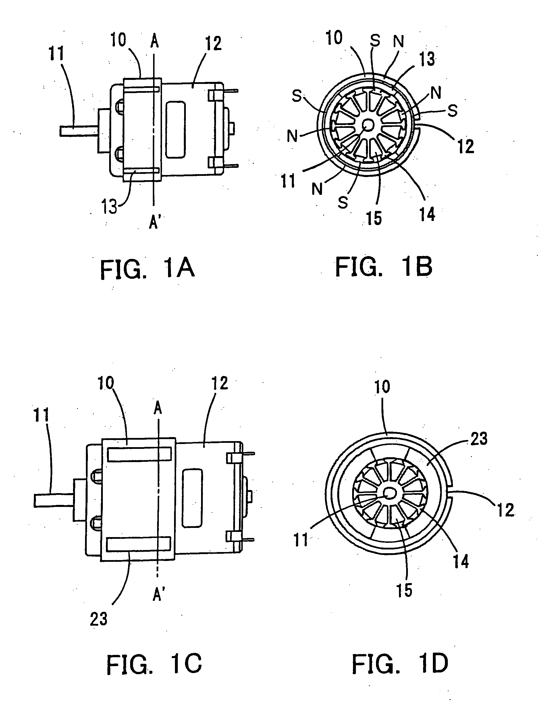
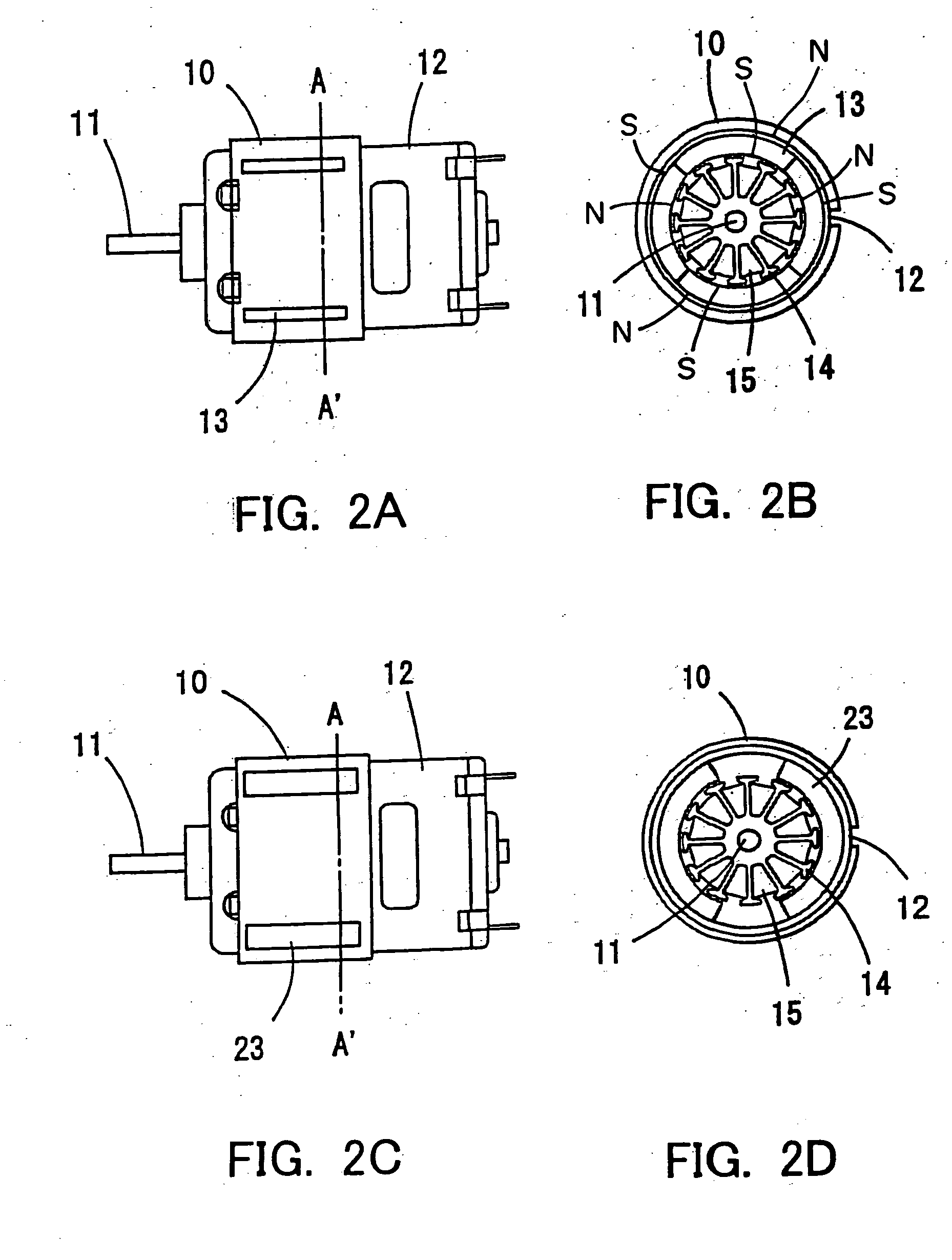
[0105] The abovementioned embodiments are one group of examples of practical forms of the present invention, but many other modified examples can be thought of. For example, in the abovementioned embodiment the anisotropic rare earth bonded magnet 13 was magnetized in a 4-pole configuration, but greater than 4 poles is also acceptable. For example, 6poles or8poles are acceptable. If the number of magnetic poles is increased, the magnetic path length gets shorter and therefore the magnetic flux across the armature coils is increased. Moreover, because it is possible to easily magnetize anisotropic rare earth bonded magnet 13, a higher power, quiet motor can be realized.

[0106] Moreover, in the abovementioned embodiment, the anisotropic rare earth bonded magnet 13 is made by resin forming, but it is also acceptable to further process the magnet after resin forming via trimming, etc. for higher precision. With increased dimension precision, a quiet motor without uneven torque is possibl...


PUM


Abstract

The challenge to be solved by the present invention is the miniaturization of a 1-300 W class of motor. This can be achieved by using a hollow-cylinder shaped anisotropic bonded magnet magnetized in a 4-pole configuration. The anisotropic bonded magnet has a maximum energy product approximately 4 times greater than the conventional sintered ferrite magnets. The use of a 4-pole configuration shortens the magnetic path length of the individual magnetic circuits and the magnetic force contributing to the torque is increased. When the torque is kept the same as in the conventional motor, the length of the electromagnetic rotor core and the axial magnet length can be reduced. In this fashion, 1-300 W class motors can be reduced in size.

Description

[0001] This is a patent application based on Japanese patent applications No. 2002-276194 and No. 2001-375159which were filed on Sep. 20, 2002 and Dec. 10, 2001, respectively, and which are incorporated herein by reference.[0002] 1. Field of the Invention[0003] The present invention is related to a DC brush motor and a permanent magnet used within. In particular, the present invention is related to a DC brush motor and associated permanent magnet whose small size and high torque are made possible by the use of an anisotropic rare earth bonded magnet as the permanent magnet. The present invention is very effective for example in 1-300 W high-performance small-size DC brush motor applications.[0004] 2. Background Art[0005] [Patent Document 1][0006] Published Unexamined Patent Application Number 2001-7691A[0007] [Patent Document 2][0008] U.S. Pat. No. 2,816,668[0009] [Patent Document 3][0010] U.S. Pat. No. 3,060,104[0011] Prior to 1960, small-sized motors did not use magnets, but were ...

Claims


Application Information

Patent Timeline
IPC IPC(8): H01F7/02H02K1/02H02K1/17H02K15/03H02K23/04
CPCH01F7/021H02K23/04H02K1/17H02K1/02
Inventor HONKURA, YOSHINOBUHASHIMOTO, YOJIMITARAI, HIRONARI
Owner AICHI STEEL
Why Eureka
Try Eureka