Process for production of alcohols

a technology for alcohol production and process, applied in the direction of climate sustainability, chemical industry, organic compound preparation, etc., can solve the problem of requiring several expensive steps

Inactive Publication Date: 2004-09-02
THE GOVERNORS OF THE UNIV OF ALBERTA
View PDF10 Cites 12 Cited by
  • Summary
  • Abstract
  • Description
  • Claims
  • Application Information

AI Technical Summary

Benefits of technology

0054] The equipment and method for the simultaneous hydration of an olefin to a corresponding secondary alcohol and recovery of the alcohol will now be described with reference to FIGS. 1 through 5. The invention will then be illustrated using a series of non-limiting examples to illustrate procedures and conditions applicable to specific alcohols, with reference to FIGS. 1 through 13.
0055] The present invention provides a method for the continuous and simultaneous catalytic hydration of an olefin to a product mixture rich in an alcohol corresponding to the olefin, and removal of the product mixture rich in alcohol from the reaction mixture. A first embodiment of equipment 10 for said method for hydration of an olefin to the corresponding alcohol will be described with reference to FIGS. 1 and 2. A second embodiment of equipment 100 for said process will be described with reference to FIGS. 3 and 4. A component that is common to each of first embodiment of equipment 10 and second embodiment of equipment 100 will be identified using the same reference numeral. One PRIOR ART process for the hydration of an olefin to the corresponding alcohol is illustrated in FIG. 5, for purpose of comparison with the process of the present invention.
0056] Referring to FIG. 1, first embodiment of equipment 10 for continuous and simultaneous hydration of an olefin to a corresponding alcohol and recovery of said alcohol as a liquid product comprises a catalytic distillation column 12, an olefin feed system 14, a water feed system 16, a liquid product recovery system 18, and a volatiles recovery system 20.
0057] Referring to FIG. 2, catalytic distillation column 12 has a body 22 having elongate cylindrical sidewalls 24, a top 26 and a base 28 defining an interior cavity 30. Body 22 is constructed of a material that is unaffected by the components of a reaction mixture contained within interior cavity 30. Body 22 can be insulated so as to maintain and withstand a temperature at which a reaction is conducted within interior cavity 30. Body 22 is capable of containing a pressurized reaction mixture at a pressure at which the reaction is conducted. Interior cavity 30 has a first portion 32, a second portion 34, and a third portion 36. Second portion 34 serves as a reaction zone during a catalytic distillation process. The reaction zone is the portion of body 22 in which essentially all of the olefin is converted to the corresponding alcohol. At least one catalyst bed 40 is situated within second portion 34. Catalyst bed 40 contains packed material comprising an active olefin hydration catalyst 42. Rectification of the volatile components of the reaction mixture occurs in first portion 32 during the catalytic distillation process. First section 32 is sized so that heavier components of the mixture can be separated from unreacted volatiles and fall toward second section 34. Third section 36 serves as a stripping section. Third section is sized so that an alcohol product 64 from the catalytic distillation process can be separated from a reaction mixture as a condensate and fall as a liquid 66 toward base 28.
0058] Referring to FIG. 1, olefins feed system 14 feeds an olefin 44 to catalytic distillation column 12. Olefin 44 is fed under pressure in a direction indicated by arrows 46 via sequentially a first olefin feed line 48, and a second olefin feed line 52 through sidewalls 24 into interior cavity 30 of body 22 of catalytic distillation column 12 at a position closely below catalyst bed 40. Water feed system 16 includes a heat exchanger 60 whereby heat is recovered from liquids recovery system 18. Water 54 is fed under pressure in a direction indicated by arrows 56 via sequentially a first water feed line 58, heat exchanger 60, and a second water feed line 62 through sidewalls 24 into interior cavity 30 at a position closely above catalyst bed 40. Olefin 44 and water 54 react over catalyst 42 in catalyst bed 40 to produce a product mixture according to Equations 1 and 2.
0059] Preferably, as shown in FIG. 2, the water is fed to body 22 at a position above reaction zone 34 and the olefin is fed to body 22 at a position below reaction zone 34. As the olefin rises through the reaction zone 34 it contacts the catalyst and is converted to the corresponding alcohol. The corresponding alcohol may then be dissolved in the descending water stream passing through reaction zone 34.

Problems solved by technology

The isopropanol must then be recovered from the fluid of the countercurrent stream or from the extraction fluid, frequently requiring several expensive steps.

Method used


Image

  • Process for production of alcohols
  • Process for production of alcohols
  • Process for production of alcohols

Examples


example 1

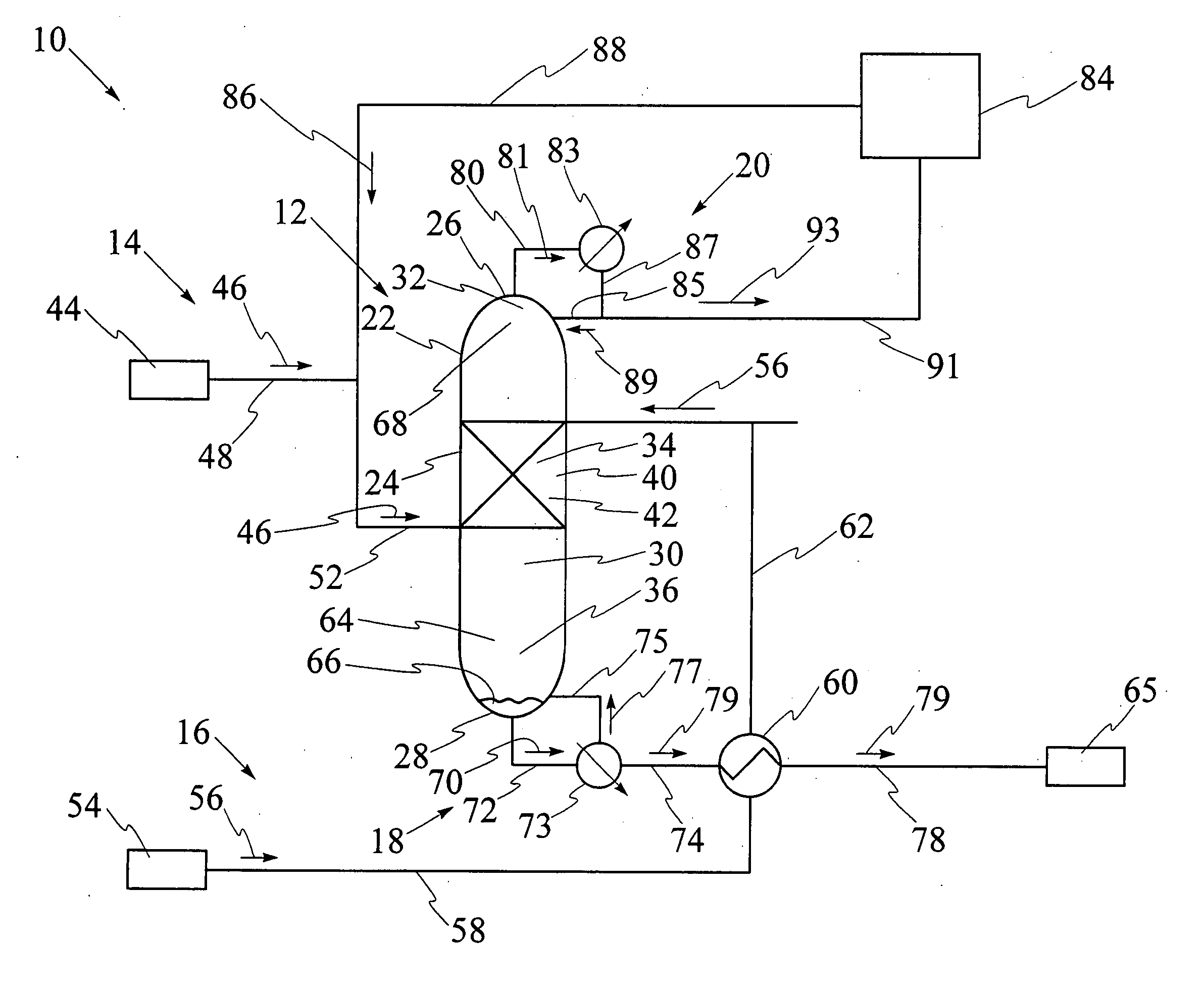
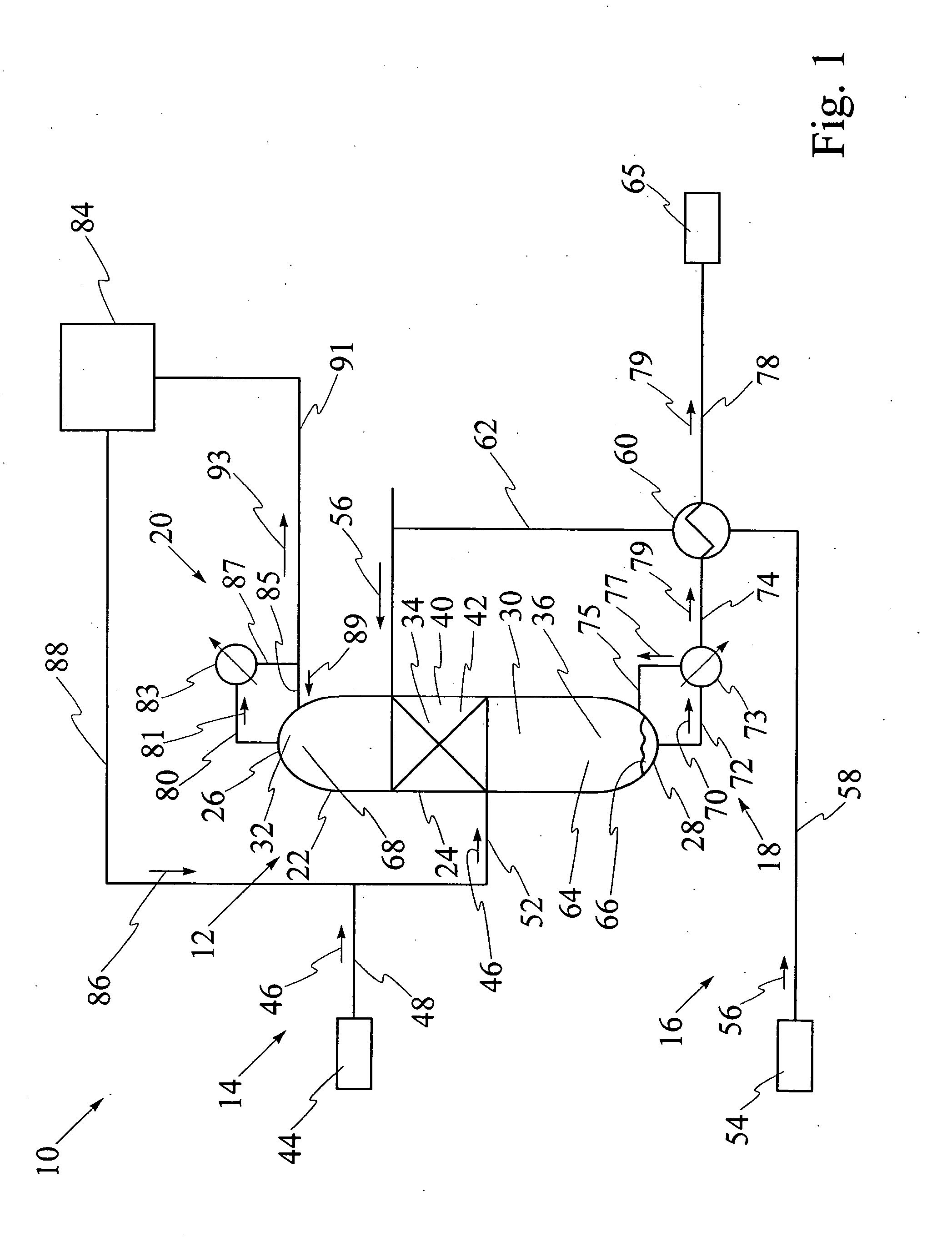
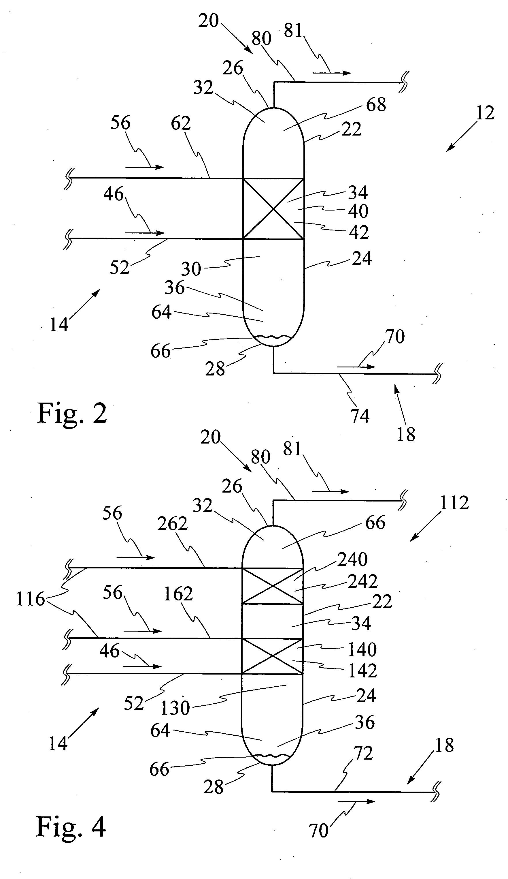
[0092] Referring to FIG. 9, catalytic distillation column 12 having single catalyst bed 40 has been used for hydration of propene to isopropanol at a pressure of 2 megaPascals. The reaction mixture includes propene, water, isopropanol and di-isopropyl ether, also known as DIPE. The computer model was run for catalytic distillation column having the dimensions illustrated in FIG. 9. It has been found that catalytic distillation column 12 having the above dimensions is effective for separation of propene at top 26 and liquid isopropanol at base 28. First portion 32 of interior cavity 30 has four stages for rectification of volatiles. Stage 5 which is shown in FIGS. 6 and 7, comprises a second portion 34 of interior cavity 30 and contains catalyst bed, 40. Third portion 36 of interior cavity 30 comprises stage 6 through stage 26, for stripping liquid isopropanol from the reaction mixture. The temperatures at stage 1, stage 26, and at catalyst bed 40 at stage 5 respectively are 50.degre...

example 2

[0093] Referring to FIG. 10, catalytic distillation column 12 having substantially the same design and size as in Example 1 has been used for hydration of propene to isopropanol at a pressure of 4 megapascals. The computer model has been used to determine that the temperatures at stage 1, stage 26, and at catalyst bed 40 at stage 5 respectively are 85.degree. C., 218.degree. C. and 169.6.degree. C., as illustrated in FIG. 10. The molar feed rates for propene and water and the recovery rates for propene and isopropanol are each illustrated as values in kilomoles per hour. Propene conversion is 35%, water conversion is 96.7%, and the purity of the isopropanol stream is over 95%, with 5% DIPE, under these operating conditions.

example 3

[0094] Referring to FIG. 11, catalytic distillation column 112 having two spaced apart catalyst beds 140 and 240 has been used for hydration of propene to isopropanol at a pressure of 2 megaPascals. The computer model was run for catalytic distillation column having the dimensions illustrated in FIG. 11. First portion 32 of interior cavity has two stages for rectification of volatiles. Referring to FIGS. 6 and 7, second portion 34 contains first catalyst bed 140 at stage 5 and second catalyst bed 240 at stage 3, first catalyst bed 140 and second catalyst bed 240 being spaced apart by stage 4. Third portion 36 comprises stage 6 through stage 26, for stripping liquid isopropanol from the reaction mixture. The temperatures at stage 1, stage 28, at first catalyst bed at stage 5 and at second catalyst bed at stage 3 respectively are 50.degree. C., 187.degree. C., 137.degree. C. and 132.degree. C., as illustrated. The molar feed rates for propene and water and the recovery rates for prope...


PUM

PropertyMeasurementUnit
pressureaaaaaaaaaa
temperatureaaaaaaaaaa
pressureaaaaaaaaaa

Abstract

The invention disclosed relates to the production of alcohols. A first aspect of the invention relates to a process for production of alcohols, and in particular to a process for the catalytic hydration of an olefin to the corresponding alcohol in substantially anhydrous form, under selected mild reaction conditions, and using a selected catalyst. A second aspect of the invention relates to a process for dehydration of an azeotropic mixture, including a first alcohol and water. A hydration reaction between the water in the azeotropic mixture and an added olefin, under selected mild conditions, and using a selected catalyst, produces a product including a second alcohol corresponding to the olefin, and the first alcohol, in substantially anhydrous form.

Description

[0001] This application is a continuation-in-part of U.S. patent application Ser. No. 09 / 918,474 filed on Aug. 1, 2001, which is still pending.[0002] A first aspect of the present invention relates to a process for production of alcohols, and in particular to a process for the catalytic hydration of an olefin to the corresponding alcohol.[0003] A second aspect of the present invention relates to a process for dehydration of an azeotropic mixture including a first alcohol and water to produce the first alcohol in a substantially anhydrous state.[0004] Several processes are known for the conversion of ethylene, higher olefins, and combinations of olefins to the corresponding alcohol by a hydration reaction. Typically, the hydration reaction produces a product mixture comprising an alcohol and an ether, each having the same carbon chain length as the olefin, in equilibrium with the olefin and water or steam. The thermodynamics and hence the equilibrium of the hydration reaction is such...

Claims


Application Information

Patent Timeline
Patent Type & Authority Applications(United States)
IPC IPC(8): C07C29/04
CPCC07C29/04C07C31/10C07C31/12Y02P20/10
Inventor CHUANG, KARL T.CHEN, YUNG F.
Owner THE GOVERNORS OF THE UNIV OF ALBERTA
Why Eureka
Try Eureka