
Sound-proof wall made of frp, and method of producing the same

a technology of frp and soundproof walls, which is applied in the direction of walls, girders, transportation and packaging, etc., can solve the problems of deterioration, cracks and gaps in the walls, and flaking of small concrete pieces,

Inactive Publication Date: 2004-07-08
TORAY IND INC
View PDF14 Cites 36 Cited by
  • Summary
  • Abstract
  • Description
  • Claims
  • Application Information

AI Technical Summary

Benefits of technology

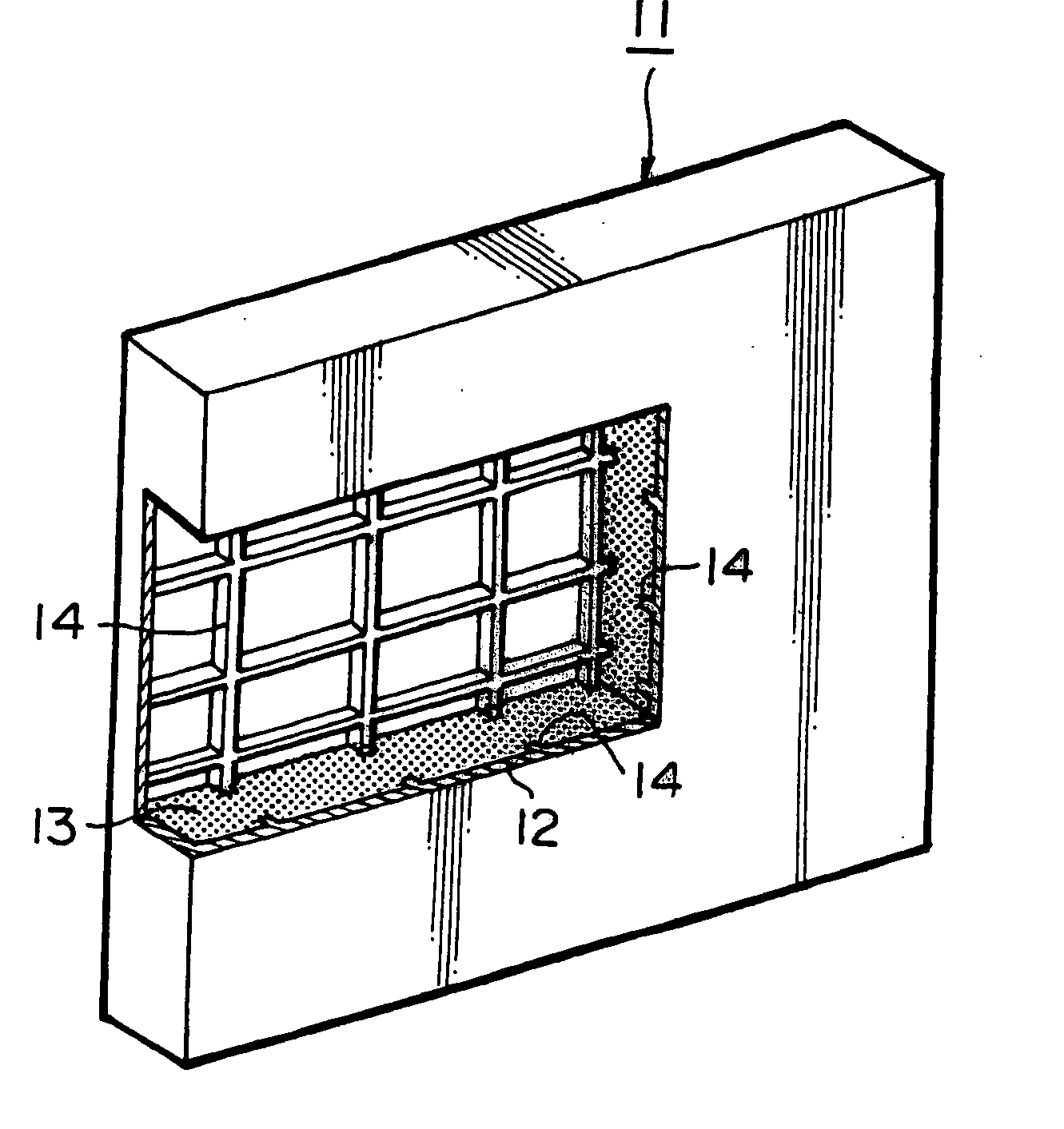
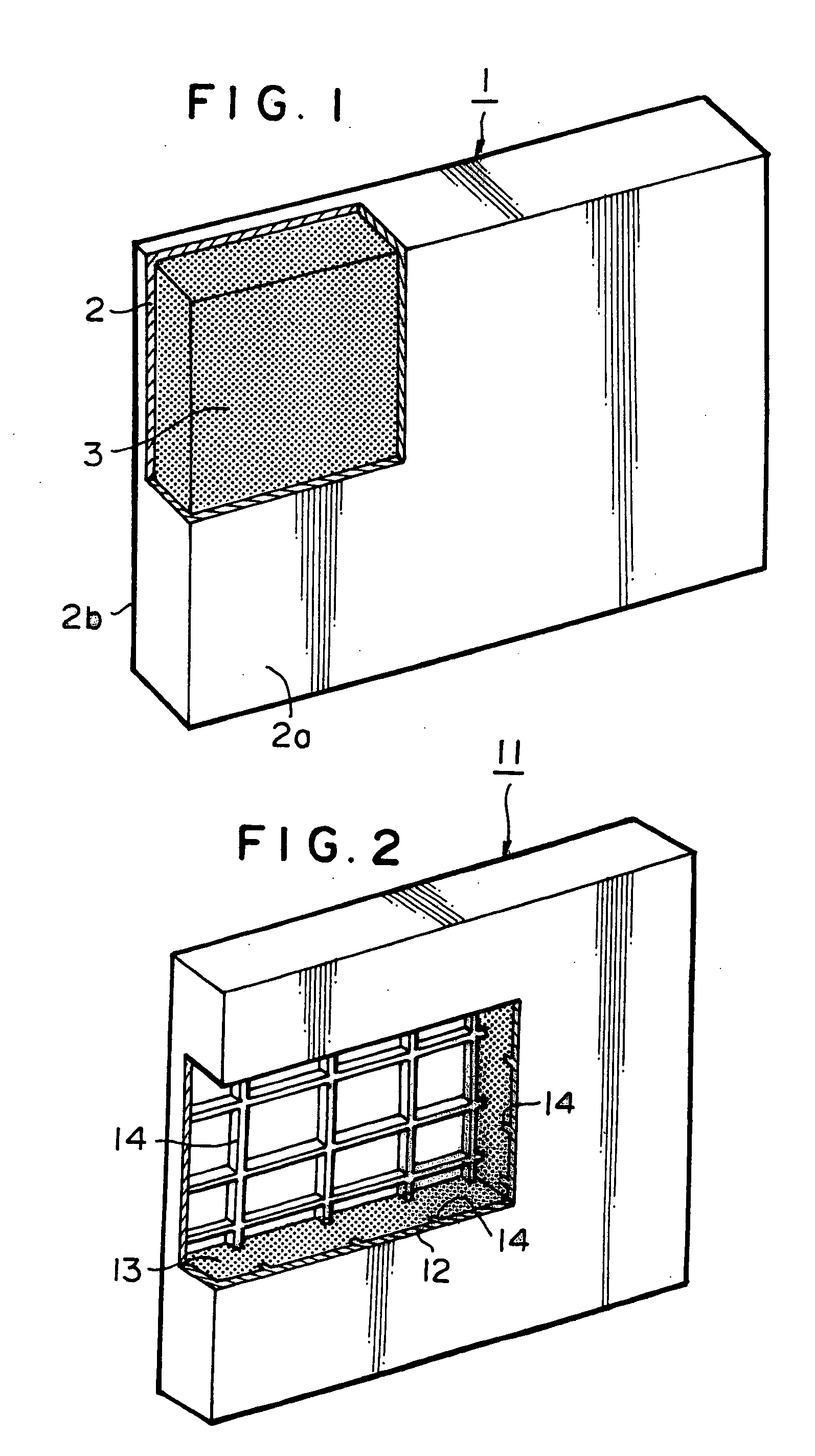
[0014] Where, there are two kinds of members of a sound insulation member and a sound absorbing member as sound-proof materials of the panel for preventing noise, and for example, when the above-described panel is formed as a three-layer structure of an FRP sound insulation panel portion, a sound absorbing body and an FRP perforated panel portion, because the energy of a sound entering from the perforated panel portion is damped by the sound absorbing body and the energy is further damped by the sound insulation panel portion, more preferable sound-proof effect can be obtained.

Problems solved by technology

Since such panels made of these materials are heavy, although they have certain effects for preventing or diffusing noise generated from trains or cars depending on mass low, in a case of a metal sound-proof panel, there is a problem in durability such as deterioration, and in a case of a concrete sound-proof panel, recently there is a problem of flaking of small concrete pieces due to bulging or cracking caused by caustic embrittlement or rust of reinforcing steel.
In particular, in a case of sound-proof walls made of concrete blocks, damage to the walls such as cracks and gaps is severe, and in a case where the installation place is at a high level such as a high-level bridge of a railway, flaking thereof becomes a problem, and therefore, urgent exchange is considered to be necessary.
Especially, in a case where the installation place is a high-level bridge of railway, there remain a problem that it is difficult to approach the exclusive construction machine to the installation place of sound-proof walls from the railway line side, and a problem in workability because, even if the approach becomes possible, the work for installation inevitably becomes a high-level place working from a position under the high-level bridge.
However, in order to use the sound-proof panels as those for railways or roads, because noise sources are relatively close and the noise levels are high, it is necessary to control their weights at proper weights based on mass low.
Namely, a light-weight sound-proof panel cannot be obtained unless an optimum design is performed with respect to sound insulation property and strength while an attachment means to a construction body such as a high-level bridge, a bridge or an edge of a road is considered.
Further, in a case where the installation place is a high-level bridge such as a high-level bridge of railway, the panel itself may become a great noise source unless a resonance due to a vibration propagated from the construction body when a train is running is avoided.
However, the present construction body or beam has a weight limitation ascribed to the viewpoint of strength, and the height of the panel cannot be increased to a height more than a certain level.
Further, although a light sound-proof panel made of acrylic is employed in consideration of such a weight limitation, there are a problem of durability due to a strength reduction ascribed to a deterioration by ultraviolet ray in a relatively short period, and a problem that the construction cost is not always cheep as a whole, because the strength and the stiffness are small and it is necessary to provide support poles and cross beams at a small interval though the sound-proof panel itself is light.
Although this panel appears to be excellent in sound insulation property, because the sound insulation panel itself is made of concrete, there is still a problem of the aforementioned partial flaking or dropping of small pieces due to caustic embrittlement or temporal deterioration.
Although it is tried to cover concrete with glass fiber reinforced plastic and prevent the flaking, it has not yet reached an essential improvement.

Method used


Image

  • Sound-proof wall made of frp, and method of producing the same
  • Sound-proof wall made of frp, and method of producing the same
  • Sound-proof wall made of frp, and method of producing the same

Examples


example 1

[0130] Woven fabrics of glass fibers with an orientation of 0 / 90.degree. and unidirectional woven fabrics of carbon fibers were stacked as reinforcing fibers of FRP skin members, multiaxial woven fabrics of glass fibers with an orientation of 0 / .+-.45.degree. were disposed for forming reinforcing ribs, and by using a 30 times foamed hard polyurethane foamed body as a core and by impregnating and curing a flame-proof unsaturated polyester resin added with 20 parts of a boromic-group halogenated organic substance (DBDPO) by a vacuum injection and impregnation molding method, an FRP sound-proof wall body as shown in FIG. 8 and having a height of 1525 mm, a width of 990 mm and a total thickness of the sound-proof portion of 56 mm was obtained. At this juncture, the total weight of the structural body (the same body as that of panel 2 of Example 4 described later) was 20.6 kg, and the weight per unit area was 13.6 kg / m.sup.2.

[0131] When this molded body was attached to a base frame so th...

example 2

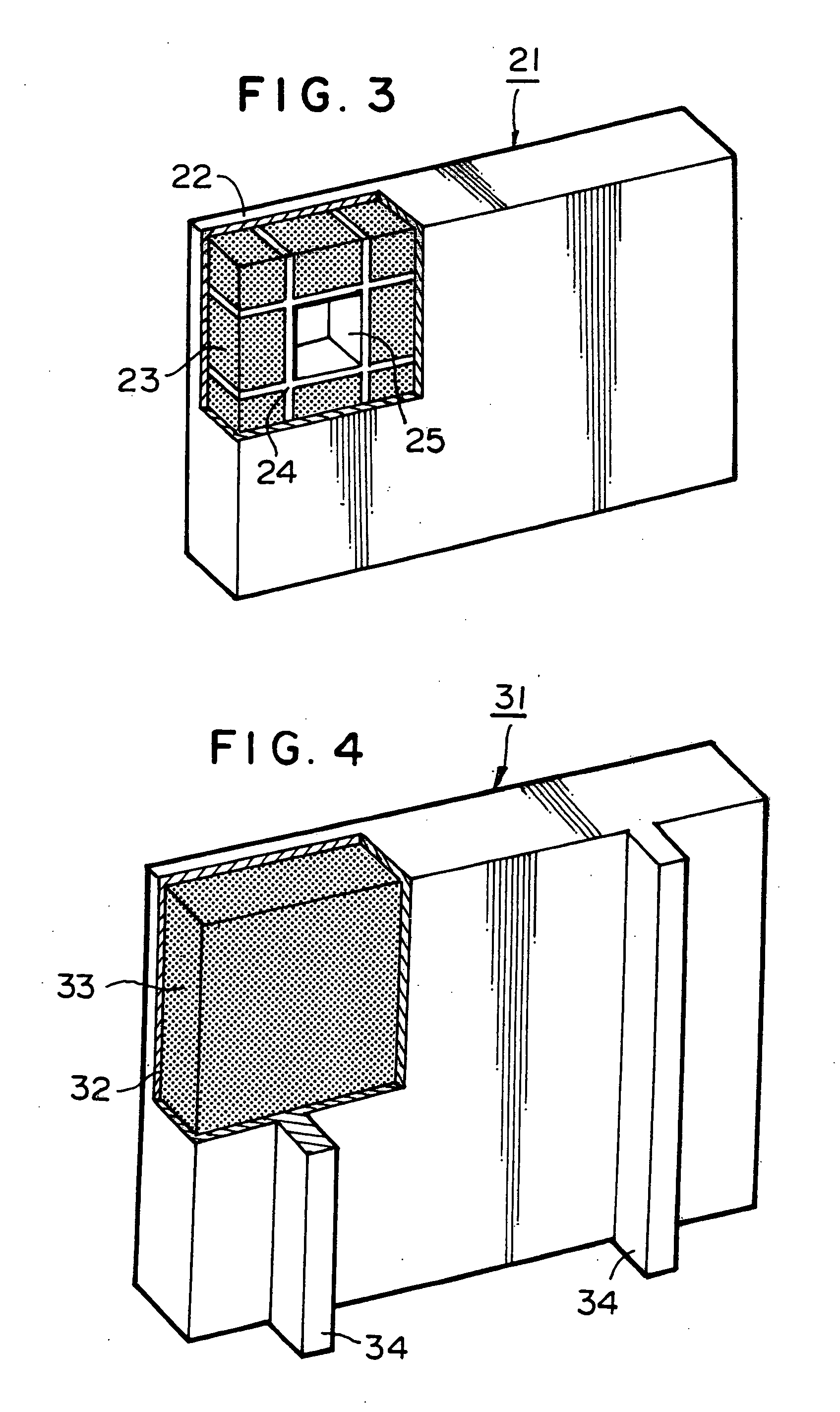
[0132] Employing similar substrate formation and resin, and using a pipe made of SUS 304 (stainless) having a thickness of 2 mm and a rectangular section of 100 mm.times.50 mm as the support pole having an attachment portion, the pole was extended up to the top of the sound insulation portion and was molded integrally. At this juncture, the fiber direction of carbon fiber 0 degree woven fabric was oriented at 90.degree. relative to the extending direction of the SUS 304 pipe, and in the same direction as the fiber direction, ribs were disposed at four positions at a pitch of 320 mm. Further, overlapping portions as shown in FIG. 17 were formed on both ends. Thus, an FRP sound-proof wall, having a height of the sound insulation panel of 1600 mm and a total width including overlapping portions at both ends of 1040 mm, was obtained. The support pole for attachment was formed in a form shown in FIG. 6 so as to project from the lower end of the sound insulation portion by 400 mm. The tot...

example 3

[0134] A glass wool material having a thickness of 13 mm was placed as a sound absorbing body on the back surface of a sound insulation panel having the same substrate structure as that described above, and from thereabove, an FRP molded plate having a thickness of 2 mm and rectangular openings each having a size of 95 mm.times.22.5 mm with a opening rate of 85% was attached to the sound insulation panel body with tapping vises via a spacer having a height of 13 mm. When the transmission loss was determined in the same condition as that described above, an improvement of the sound insulation property by 5 dB could be achieved. The total weight of this panel was 53 kg, and the weight per unit area was 32 kg / m.sup.2.


PUM

PropertyMeasurementUnit
Fractionaaaaaaaaaa
Lengthaaaaaaaaaa
Fractionaaaaaaaaaa

Abstract

A sound-proof wall made of FRP in the form of a sound-proof wall panel that comprises a core and skin members made of FRP positioned on both sides of the core and whose weight per nit area is within the range of 10-60 kg / m<2>; and a method of producing the same. This sound-proof wall, though light in weight, has a superior sound insulation property and will never corrode because it is made of FRP. Further, it has a high degree of freedom of engineering design including sound-proof property, design, and shape, capable of producing a desired sound-proof wall with case. Further, since it has a high specific strength, it is possible to attain a drastic weight reduction while retaining the necessary strength, and facilitate working, shorten construction time, and reduce construction cost.

Description

[0001] The present invention relates to a sound-proof wall made of a fiber reinforced plastic (hereinafter, referred to as "FRP") provided to railways, roads, etc., for the purpose of insulating noises generated by trains and cars, and a method for producing the same.BACKGROUND ART OF THE INVENTION[0002] Noises induce complains and troubles most frequently among various pollutions, and prevention of noise as a countermeasure against an environmental problem is an important social subject.[0003] Generally, there are two kinds of members of a sound insulation member and a sound absorbing member as sound-proof members for preventing noise.[0004] The sound insulation member functions to cut the propagation of sound energy by reflecting a sound propagated in air, and the sound transmission loss, which is an index of the sound insulation property, basically depends on mass low, and becomes greater as the mass becomes greater. For example, mainly a concrete sound-proof panel or a metal sou...

Claims


Application Information

Patent Timeline
IPC IPC(8): E01F8/00
CPCE01F8/0017E01F8/007Y10T428/187Y10T428/24628Y10T428/24322Y10T428/24182Y10T428/24996Y10T428/249976Y10T428/249981B29C70/06E04B2/00E04C2/38
Inventor ITO, TOSHIHIROOCHI, YUTAKAKATO, TORUODANI, HIROSHITANAKA, SHINTAROYOSHIMURA, KOUSUKEOCHI, ATSUSHIMITANI, KIMIO
Owner TORAY IND INC
Learn More