
Ball grid array resistor network

a resistor network and array technology, applied in the direction of resistor details, resistive material coating, non-metallic protective coating application, etc., can solve the problems of loss of signal high frequency components, affecting the transmission of high frequency signals, and progressively worsening of signal transmission

Inactive Publication Date: 2004-06-10
CTS CORP ELKHART
View PDF30 Cites 28 Cited by
  • Summary
  • Abstract
  • Description
  • Claims
  • Application Information

AI Technical Summary

Problems solved by technology

Unfortunately, as the frequency of the signal increases, or as the frequency of component signals that act as a composite increases, the characteristics of most common transmission lines decay and signal transmission progressively worsens.
One common phenomenon associated with high frequency, long distance transmission lines is a loss of the signal's high frequency components and the introduction of extraneously induced interfering high frequency signals.
In the case of a digital pulse, the effect will lead to corrupted data, since additional pulses may be received that were not part of the original transmission, and reflected pulses may cancel subsequent pulses.
These high frequency busses are, in particular, very susceptible to inappropriate termination and transmission line echo.
The prior art has attempted to address signal line termination in a number of ways which were suitable at lower operating speeds and frequencies, but which have not proven fully desirable as frequencies and components thereof increase.
Furthermore, shorter line lengths decrease the undesirable cross-talk described hereinabove.
These prior art BGA devices have a high cost of production due to the fact that they are manufactured either one at a time or in small arrays and many manufacturing steps are required.

Method used


Image

  • Ball grid array resistor network
  • Ball grid array resistor network
  • Ball grid array resistor network

Examples


Embodiment Construction

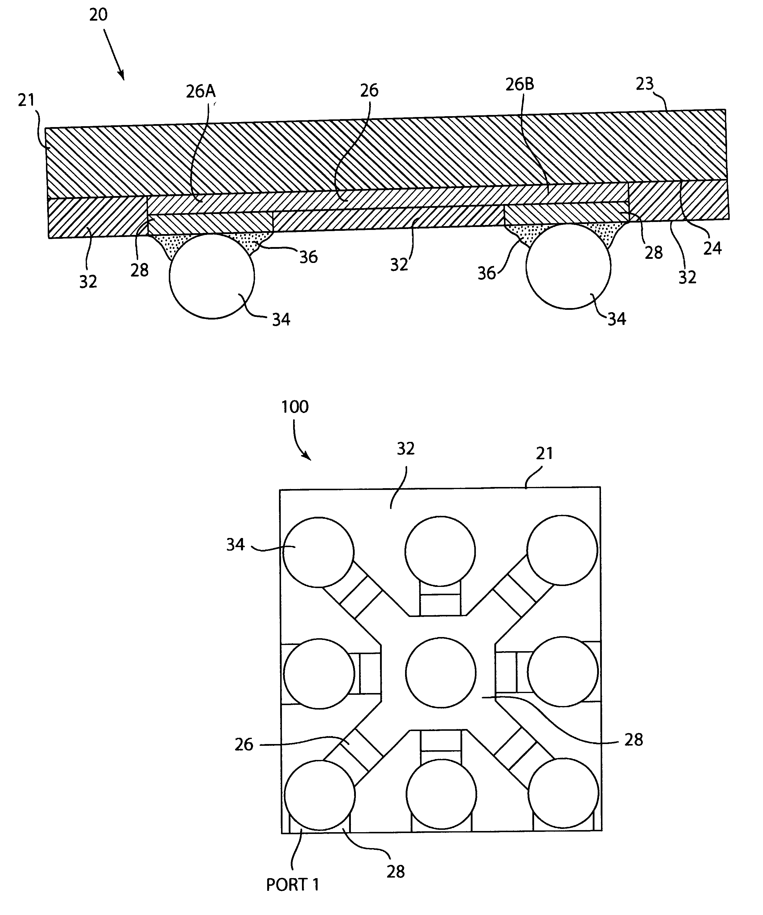
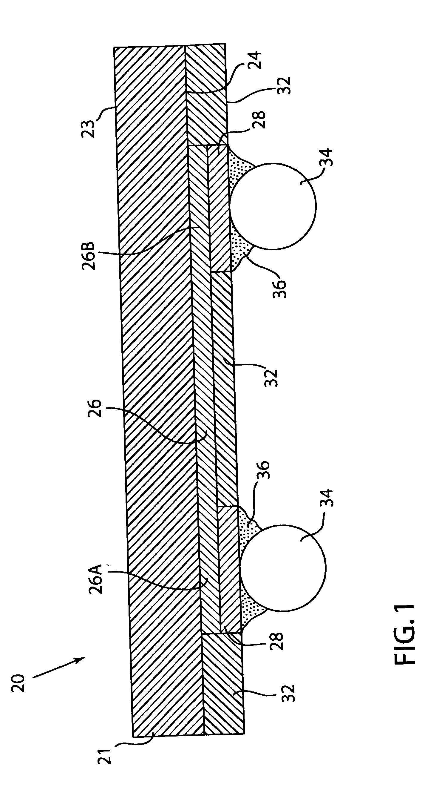
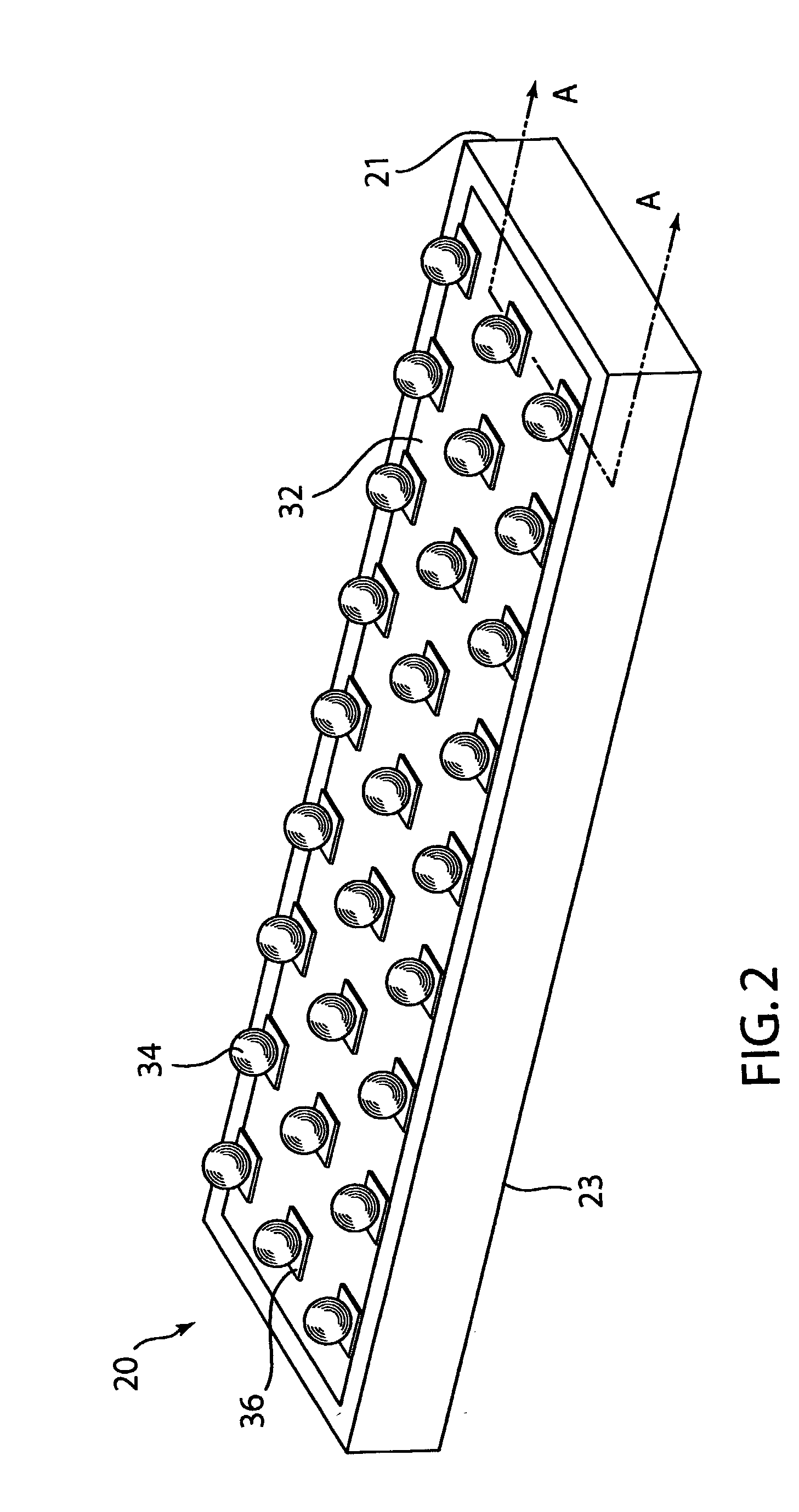
[0039] Referring to FIGS. 1 and 2, a Ball Grid Array Resistor Network (BGA) 20 is shown. Network 20 has a planar substrate or printed wiring board 21 formed from an organic polymer material. Substrate 21 has a top surface 23 and a bottom surface 24. Substrate 21 can be formed from various organic materials such as FR4, Polyimide and other insulative dielectrics.

[0040] Printed wiring board 21 includes a non-conductive substrate and copper traces. The non-conductive substrate is preferably a composite material, for example, epoxy-glass, phenolic-paper, or polyester-glass; and typical composites used in circuit board manufacturing include polyimides for flexible circuitry or high-temperature applications; paper / phenolic which can be readily punched: National Electrical Manufacturers Association (NEMA) grade FR-2; paper / epoxy which has better mechanical properties than the paper / phenolic: NEMA grade FR-3; glass / epoxy and woven glass fabric which have good mechanical properties: NEMA gra...


PUM


Abstract

A ball grid array resistor network has a planar substrate formed of an organic material. The substrate preferably is a printed circuit board. The substrate has a top and bottom surface. A ball pad is located on the bottom surface. A low temperature resistor is located on the bottom surface and is connected to the ball pad. A solder mask is located over the first surface except for the ball pads. A conductive ball is attached to the ball pad. A reflowed solder paste connects the conductive ball to the ball pad. Several embodiments of the invention are shown.

Description

[0001] 1. Field of the Invention[0002] This invention pertains generally to resistor networks for terminating transmission lines and electronic devices and more specifically to a resistor network that is formed on an organic substrate.[0003] 2. Description of the Related Art[0004] Transmission lines are used in a diverse array of electronic equipment to accommodate transmission of electrical or electronic signals. These signals may have a diverse set of characteristics, which might, for example, include direct or alternating currents, analog or digitally encoded content, and modulation of any of a diverse variety of types. Regardless of the characteristics of the signal, an ideal transmission line will conduct the signal from source to destination without altering or distorting the signal. Distance is inconsequential to this ideal transmission line, other than delays which might be characteristic of the transmission medium and the distance to be traversed.[0005] At low frequencies a...

Claims


Application Information

Patent Timeline
IPC IPC(8): H01C1/028H01C17/06H05K1/16H05K3/18H05K3/28H05K3/34
CPCH01C1/028H01C17/06H05K1/167H05K3/184H05K2203/1453H05K3/3436H05K2201/0355H05K2203/0361H05K2203/041H05K3/28
Inventor ERNSBERGER, CRAIGLANGHORN, JASON B.TU, YINGGANG
Owner CTS CORP ELKHART
Learn More