
Method for making ferroelectric thin film

a technology of ferroelectric thin film and ferroelectric insulating layer, which is applied in the direction of piezoelectric/electrostrictive/magnetostrictive devices, semiconductor devices, capacitors, etc., can solve the problems of short solution life, waste of excess amount of unused mixed solution, and waste of material, etc., to achieve the effect of superior ferroelectri

Inactive Publication Date: 2004-05-27
SEIKO EPSON CORP
View PDF1 Cites 11 Cited by
  • Summary
  • Abstract
  • Description
  • Claims
  • Application Information

AI Technical Summary

Benefits of technology

The present invention provides a method for making a ferroelectric thin film by inkjetting a solution containing a ferroelectric material and a paraelectric material onto a substrate. The method allows for the creation of a superior thin film with uniform mixing of the two solutions, resulting in a more uniform deposition over the film thickness. The method also allows for the creation of a thin film with different composition ratios by adjusting the discharge amount of each solution. Additionally, the method prevents uneven compositional distribution in the thin film by changing the discharge amount of each solution and estimating the uneven in-plane ferroelectric capacitor characteristics. The method further includes a hydrophilic treatment on the substrate before applying the stock solutions and a discharging time interval to ensure the next landing of the stock solutions does not occur after the previous landing has dried. The method also allows for the formation of a highly rectangular hysteresis curve by preventing the formation of a 90-degree domain. The invention also provides a method for making the ferroelectric device by inkjetting the solutions onto the substrate.

Problems solved by technology

However, use of the mixed solution causes several problems.
Because the shelf life of the solution is short in general, the mixed solution cannot be stored for a long time.
For the same reason, an excess amount of unused mixed solution incurs waste of the material.
Unfortunately, many kinds of solutions having different element concentrations are needed to achieve improved homogeneity by spin coating.
Furthermore, after the process for making a ferroelectric capacitor, the properties of the ferroelectric capacitor in a plane are uneven due to the in-plane distribution of the temperature during the firing process.
Another disadvantage in spin coating is that the distribution of the stock solution composition cannot be varied in the plane direction.

Method used


Image

  • Method for making ferroelectric thin film
  • Method for making ferroelectric thin film
  • Method for making ferroelectric thin film

Examples


example 2

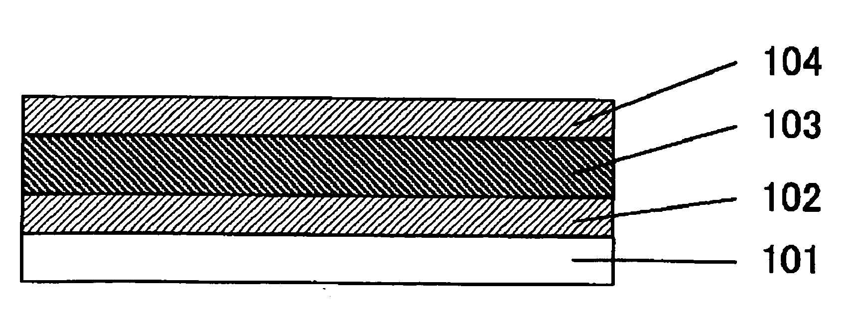
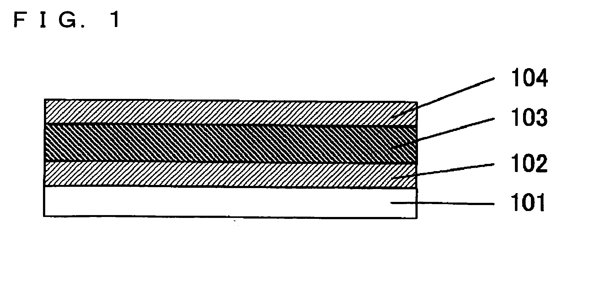
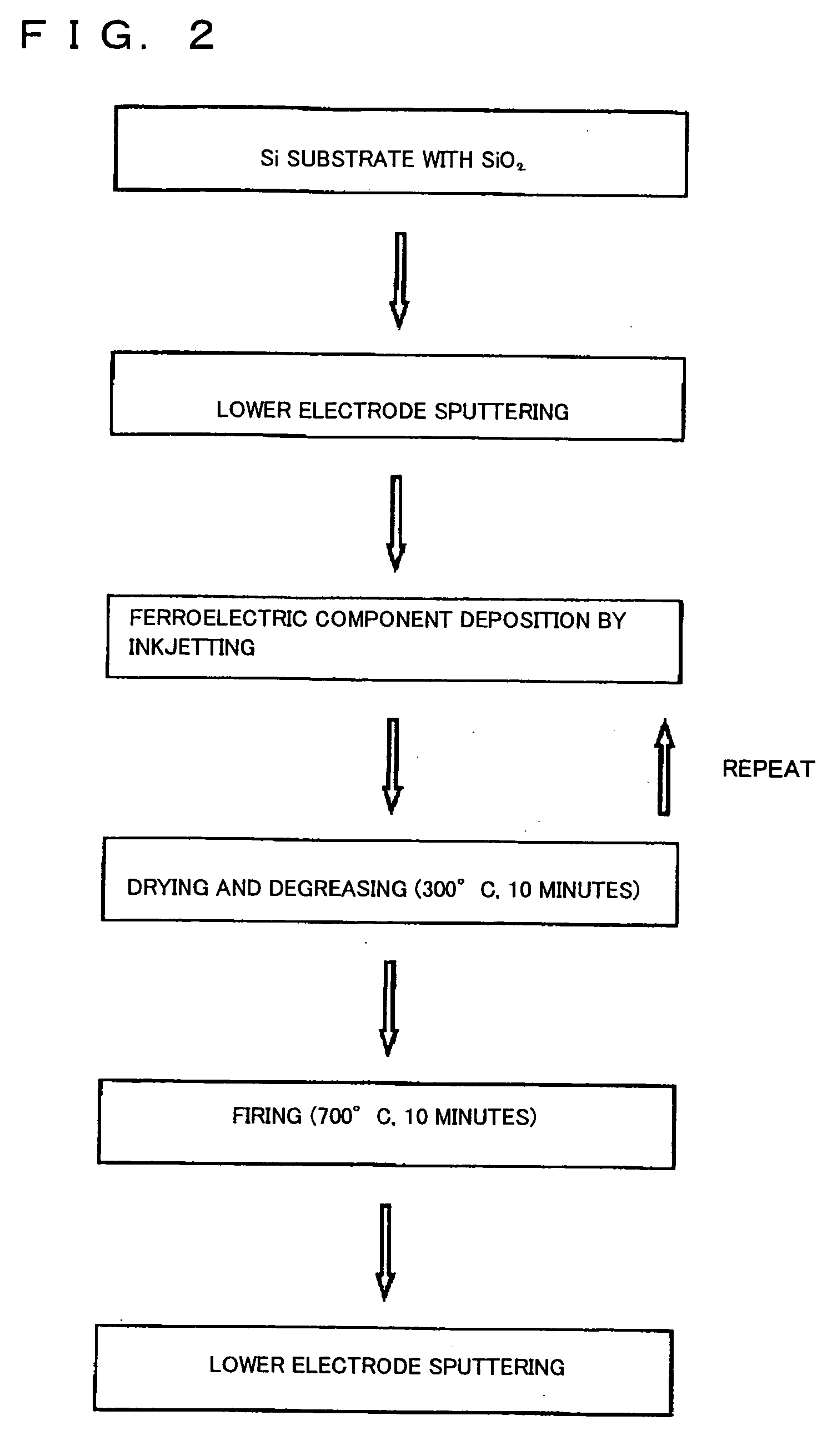
[0033] An example in which two PZT solutions (composition ratio: Pb / Zr / Ti=120 / 35 / 65 and 110 / 35 / 65) were used as the ferroelectric material is described. Hereinafter the PZT solution having the composition Pb / Zr / Ti=120 / 35 / 65 and the PZT solution having the composition Pb / Zr / Ti=110 / 35 / 65 are referred to as Solution X and Solution Y, respectively. At first, a lower electrode was deposited on a substrate, and then the substrate was pre-baked on a hotplate and was cooled, as in Example 1. Then Solution X and Solution Y were applied regularly in lines, as shown in FIG. 3, with separate inkjet heads of an inkjet apparatus. The discharge time intervals of Solution X and Solution Y by the inkjet apparatus were set so that the next landing occurred a sufficient of time before the previous landing had dried. A cycle including five continuous applications was repeated six times to form a film thickness of 120 nm after firing. The discharge ratio of Solution X to Solution Y (Solution X / Solution ...

example 3

[0037] The hysteresis characteristic of Sample E in Example 2 and Sample F having a distribution of Solution X and Solution Y in Example 2 were measured at five random points. Sample E was used to examine the in-plane distribution of the ferroelectric capacitor, and Sample F was used to feed back the in-plane distribution in the thermal process among the entire process. It is noted that Sample F did not have a distribution of Solution X and Solution Y over the thickness, and the fabrication conditions of Sample F were identical to that of Sample E except for the deposition condition of the ferroelectric thin film.

[0038] FIG. 8 and FIG. 9 show the hysteresis curves at five random points of Sample E and Sample F, respectively. It was found that while the hysteresis characteristic of Sample E, in which the PZT solution (Solution Z in Example 2) was homogeneously applied in plane, has a distribution in the plane, the hysteresis characteristic of Sample F, having a distribution of Soluti...


PUM


Abstract

A ferroelectric thin film comprising at least two stock solutions is made so that the stock solutions are mixed homogeneously in the plane and over the thickness on a substrate, or so that the stock solutions are mixed having a distribution in the plane and over the thickness on the substrate. A ferroelectric thin film mixed homogeneously in the plane is made by discharging two stock solutions 105 and 106 separately at a fixed discharging rate by separate inkjet heads using an inkjet apparatus having at least two inkjet heads, and a ferroelectric thin film mixed homogeneously over the thickness is made by repeating this process. Moreover, a ferroelectric thin film having a distribution of the stock solutions is made by changing the discharging rate in the thickness direction or the in-plane direction.

Description

[0001] The present invention relates to ceramic thin films used in ferroelectric devices, piezoelectric devices, and the like. In particular, the present invention relates to a method for making ceramic thin films using at least two stock solutions.[0002] When a ferroelectric solution and a paraelectric solution are used as stock solutions in the formation of a ferroelectric thin film, these stock solutions are preliminarily mixed so that the mixed solution can be applied to a surface as a homogeneous mixture by spin coating or dipping, which are typical known film formation methods. However, use of the mixed solution causes several problems. Because the shelf life of the solution is short in general, the mixed solution cannot be stored for a long time. For the same reason, an excess amount of unused mixed solution incurs waste of the material.[0003] As disclosed in Japanese Unexamined Patent Application Publication No. 5-235268, a uniform concentration of elements is achieved over ...

Claims


Application Information

Patent Timeline
Patent Type & Authority Applications(United States)
IPC IPC(8): H01L41/09H01L21/02H01L21/314H01L21/316H01L21/8246H01L27/105H01L41/317H01L41/39
CPCH01L21/31691H01L41/317H01L41/1876H01L28/55H01L21/02282H01L21/02197H10N30/8554H10N30/077H01L21/31
Inventor KUROKAWA, KENICHINATORI, EIJI
Owner SEIKO EPSON CORP
Learn More