
Integrated analytical biochip and manufacturing method thereof

a biochip and integrated technology, applied in the field of integrated analytical biochips and their manufacturing, can solve the problems of inability to provide immediate and precise temperature control of the system, time-consuming and expensive manufacturing processes to be employed for deposition and etching, and inability to achieve immediate and precise temperature control. , to achieve the effect of avoiding short circuits

Inactive Publication Date: 2004-04-01
NAT CHENG KUNG UNIV
View PDF2 Cites 24 Cited by
  • Summary
  • Abstract
  • Description
  • Claims
  • Application Information

AI Technical Summary

Benefits of technology

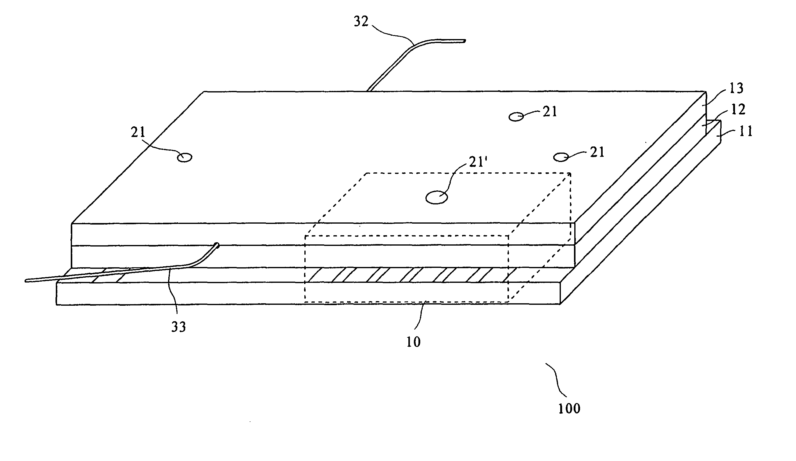
[0062] As shown in FIG. 6, the fiber structure 30 on the biochip of the present invention is provided by first forming optic fiber channels 31 and then putting optic fibers 32 and 33 therein. The location of the optic fiber channel 31 on the biochip 100 and the alignment of the optic fibers 32 and 33 are both designed so as to prevent from complicated optical alignment procedures. The manufacturing process shall be elaborated subsequently. The optic fiber 32 is a light source fiber 32, whereas the optic fiber 33 is a detecting fiber 33. The light source fiber 32 is for coupling a light source 34 (such as laser), so as to enable a detection light with a specific wavelength to project into the micro channels 20, thus causing the pre-labeled DNA sample to emit induced fluorescent signals. Subsequently a light detector 35 coupled by the detecting fiber 33 goes on to measure the intensity of fluorescence of the DNA segment passing through sections of the fiber at various periods of time. The fiber structure 30 integrated on the biochip 100 can thus avoid burdensome procedures caused by conventional optical alignment and tremendously lower expenses for detecting units, and at the same time provide accurate real-time online detection.
[0070] FIG. 9 shows a curve graph of the PCR thermal cycles of the present invention, which provides the result that as the volume of a sample is 900 nL, the temperature rising rate is 20.degree. C. / sec, the temperature cooling rate is 10.degree. C. / sec, and the average power consumption is 1.24W. The micro heater in the micro reaction tank of the present invention is capable of rising and lowering the temperature within short periods of time, with the accuracy thereof being .+-.0.1.degree. C., and precisely controlling the variation of temperature while the PCR reaction is proceeded in the micro reaction tank via the temperature control formula predetermined in advance in the IC controller.

Problems solved by technology

However, regarding reaction tanks with volume thereof less than 1 .mu.L, it is quite a challenge to try to manufacture micro temperature control system with lower production costs, lower energy consumption, simpler manufacturing processes, higher efficiency for raising and lowering temperatures and better temperature stabilization, simply because silicon chips used in semiconductor manufacturing processes are not biologically compatible, thus time-consuming and expensive manufacturing processes have to be employed for deposition and etching.
Also the temperature detector placed at the exterior of the reaction tank and the heater would cause tremendous heat inertia, such that the values obtained by the temperature detector would not be the actual temperature of the reaction sample.
Furthermore, with the blocking of the reaction tank walls, the temperature gradient between the heater and the sample is caused, thus rendering the system unable to provide immediate and precise temperature control.
Yet as the quantity of PCR samples decreases to under 1 .mu.L, the repetitious actions of injecting and retrieving would cause the decrease of the quantity of PCR samples, thus adversely affecting the detection results.
1. The alignment in the process of the optical detection is extremely complicated and time-consuming;
2. The laser source needs to be positioned, a process that is difficult and time-consuming; and
3. The conventional optical detection device is complicated and cumbersome.
Based upon the inconveniencies mentioned above, the production costs of the conventional optical detection device are too high to proceed to commercial mass production.

Method used


Image

  • Integrated analytical biochip and manufacturing method thereof
  • Integrated analytical biochip and manufacturing method thereof
  • Integrated analytical biochip and manufacturing method thereof

Examples


Embodiment Construction

[0067] The Performance Test on the Temperature Detector

[0068] This embodiment employs the integrated analytical biochip 100 shown in FIG. 1 in accordance with the IC controller and the power supplier, with the result being shown in FIG. 8, which shows a curve graph of the function of the temperature detector on the biochip of the present invention, that the values of the electrical resistance and the temperature variations form a linear correlation with the slope (Temperature coefficient of resistance, TCR) being 0.00315 / .degree. C. Thus, accurate temperature signals can be provided within the operating range of PCR temperatures.

[0069] PCR Temperature Circulation Test

[0070] FIG. 9 shows a curve graph of the PCR thermal cycles of the present invention, which provides the result that as the volume of a sample is 900 nL, the temperature rising rate is 20.degree. C. / sec, the temperature cooling rate is 10.degree. C. / sec, and the average power consumption is 1.24W. The micro heater in th...


PUM

PropertyMeasurementUnit
timeaaaaaaaaaa
total volumeaaaaaaaaaa
electric potentialaaaaaaaaaa

Abstract

The present invention provides an integrated analytical biochip and manufacturing method thereof, mainly by using a speedy and low-cost manufacturing process to integrate the Polymerase Chain Reaction ("PCR") reaction tank, Capillary Electrophoresis ("CE") channel and the fiber structure onto a single biochip, thus a DNA sample may be amplified via PCR on the biochip, and immediately driven into the CE channel for analysis in accordance with real-time online detection conducted through the fiber structure integrated on the biochip, such that a speedy and accurate process of biological sample detection and analysis can be achieved.

Description

[0001] 1. Field of the Invention[0002] The present invention provides an integrated analytical biochip and manufacturing method thereof, whereby utilizing the micro electromechanical system process for forming a Polymerase Chain Reaction ("PCR") micro-reaction tank, capillary electrophoresis ("CE") channels and a set of optic fiber structures on a biochip, and at the same time producing a micro temperature detector, a micro heater and an electrode for integrating with an IC controller, such that an integrated biological detection and analysis system can be formed on the same biochip.[0003] 2. Description of the Related Art[0004] The method of utilizing PCR to clone all kinds of DNAs has already been widely applied during pre-processing procedures in biomedical detection, and the sensitivity of biomedical detection can be increased by the quantity amplified from cloning. The traditional PCR thermal cycler is operated by placing samples contained in plastic tubes into a large PCR ther...

Claims


Application Information

Patent Timeline
Patent Type & Authority Applications(United States)
IPC IPC(8): B01L3/00B01L7/00G01N21/03G02B6/26G02B6/36G02B6/43
CPCB01L3/502707G02B6/43B01L7/52B01L2200/147B01L2300/0636B01L2300/0654B01L2300/0816B01L2300/1827B01L2400/0421G01N21/0303G01N2021/0325G01N2021/0346G02B6/262G02B6/3636G02B6/3644G02B6/3692B01L3/502715
Inventor LEE, GWO-BIN
Owner NAT CHENG KUNG UNIV
Learn More