
Micromixer with overlapping-crisscross entrance

a micromixer and cross-section technology, applied in the field of micromixers, can solve the problems of difficult mixing fluids in microfluidic systems, inability to improve mixing efficiency further, and difficulty in improving fluid mixing in microfluidic systems, so as to improve mixing performan

Inactive Publication Date: 2005-10-20
YANG JING TANG
View PDF10 Cites 36 Cited by
  • Summary
  • Abstract
  • Description
  • Claims
  • Application Information

AI Technical Summary

Benefits of technology

[0016] The present invention provides a micromixer with overlapping-crisscross entrance that merges two fluids and alters the flow motion of both at the entrance region and enlarges the contact area between the two mixing fluids and induces tumbling to generate a vertical component of flow.
[0017] Additionally, the present invention provides a micromixer with overlapping-crisscross entrance that develops a significant crossflow about the inlet port of the micromixer and grooved channels, thus improving the mixing performance near the inlet port
[0018] Furthermore, the present invention provides a micromixer with overlapping-crisscross entrance that activates a restructuring of the flow configuration and mixing patterns in the grooved microchannels.

Problems solved by technology

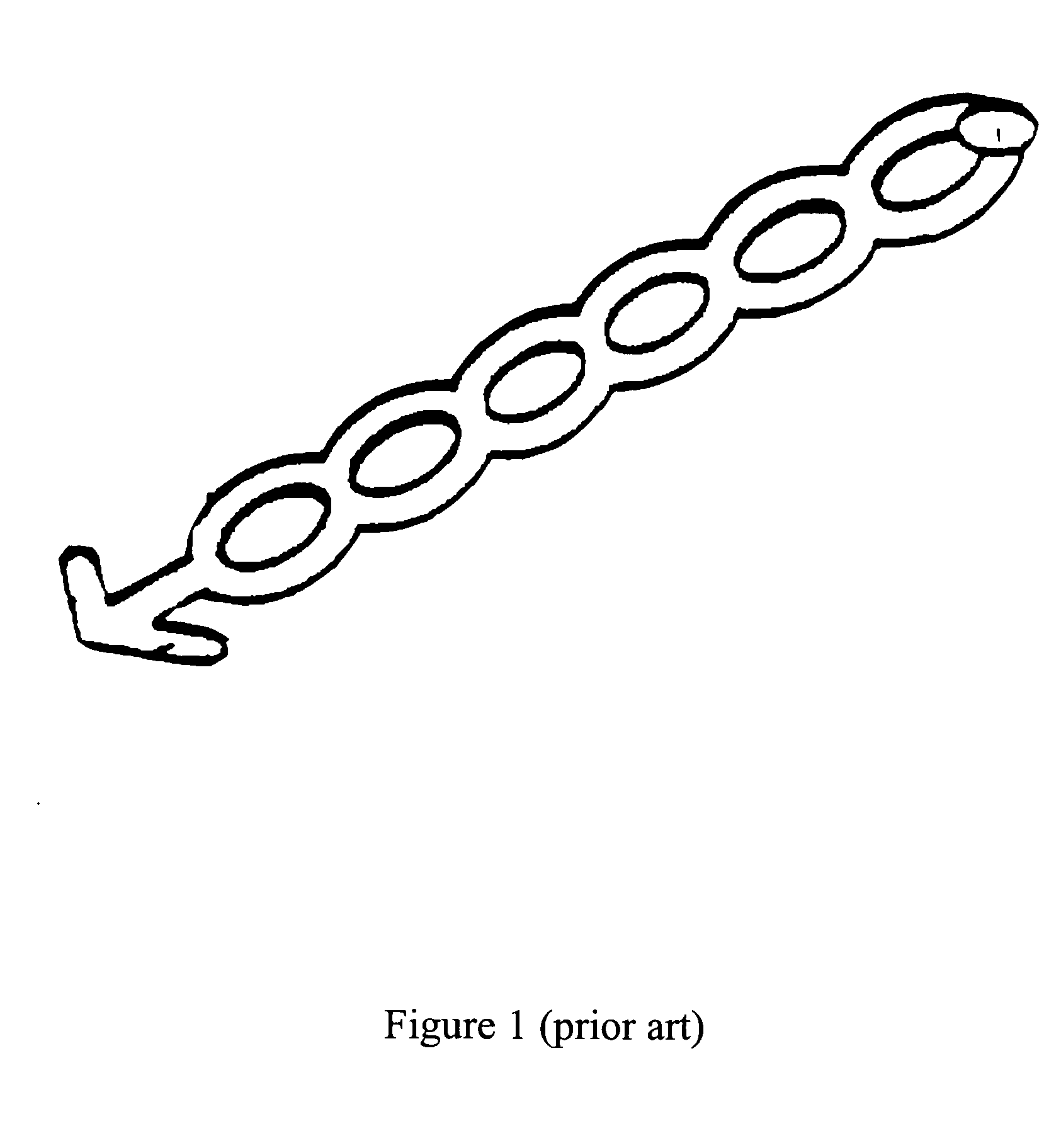
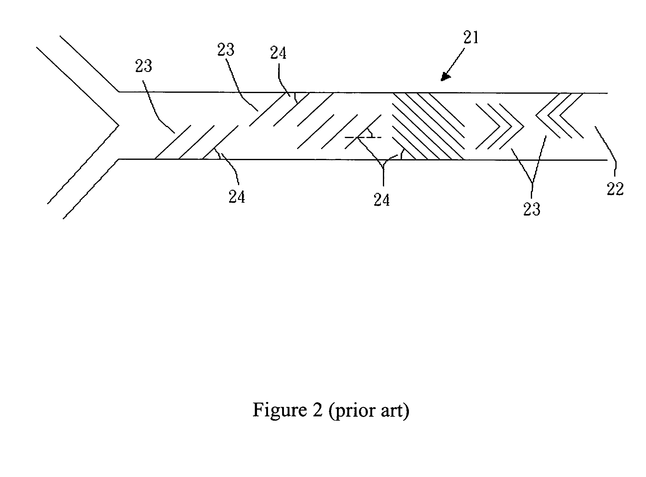
This design often causes two fluids flow separately on both sides of microchannel, and only has slowly molecular diffusion between two fluids as a consequence of having difficulties to produce folding and stretching wanted.
Lacking the bulk mixing characteristics of macroscale systems, in which increased agitation or perturbation promotes effective mixing, the enhancement of fluid mixing in microscale systems remains a problematic challenge.
However, with the effect of entrance mechanism the fluid exposed to interfacial area has not obtained big advantage of it, and is unable to improve mixing efficiency further.
Mixing fluids in a microfluidics system is difficult because of the small Reynolds number.

Method used


Image

  • Micromixer with overlapping-crisscross entrance
  • Micromixer with overlapping-crisscross entrance
  • Micromixer with overlapping-crisscross entrance

Examples


Embodiment Construction

[0036] Reference will now be made in detail to the preferred embodiments of the present invention, examples of which are illustrated in the accompanying drawings. Wherever possible, the same reference numbers are used in the drawings and the description to refer to the same or like parts.

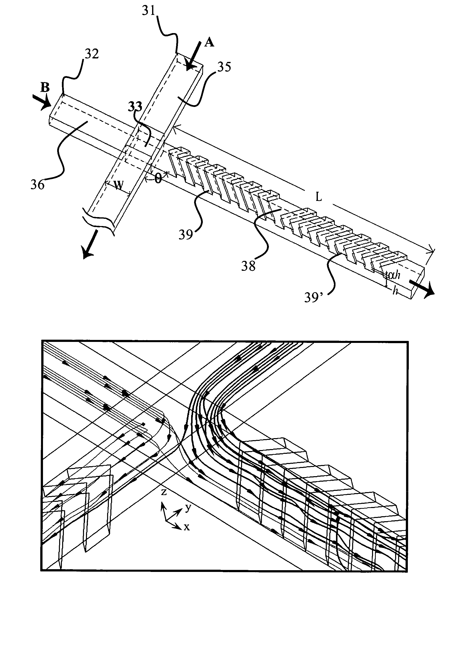
[0037] Refer to FIG. 4A, which is a schematic diagram illustrating the micromixer with overlapping-crisscross entrance according to an embodiment of the present invention.

[0038] This present invention consists of two straight, grooved microchannels crossing each other face to face in a tiny area at an angle from 0 to 180 degrees. The construction of the present invention is symmetric with respect to the contact surface between two microchannels. The transverse and longitudinal microchannels 31,32 containing fluids A and B respectively are in contact and mix across a small area 33. The width of each microchannels is about 5 μm to 500 μm and has one inlet and one outlet, wherein the aspect ratio is ...


PUM

PropertyMeasurementUnit
angleaaaaaaaaaa
angleaaaaaaaaaa
widthaaaaaaaaaa

Abstract

The micromixer with overlapping-crisscross entrance incorporated with the grooved microchannel, is used effectively for mixing two or more fluid streams. The X-shape overlapping-crisscross inlet ports wherein two microfluidic channels contact over a small area, allow the fluid streams flow through and create the tumbling inside the micromixer. Then merging with some patterned grooves on the walls also induces swirling motion. As a result, the folding and stretching effects of the flow are augmented to amplify the fluid mixing of two or more streams of the inlet fluids within a relative short distance in the micromixer. All of the flow streams are actuated with either pressure driven by a syringe pump or capillary electrophoresis. The present invention is applicable for micro total analysis systems and drug delivery systems.

Description

BACKGROUND OF THE INVENTION [0001] 1. Field of the Invention [0002] The present invention relates to a micromixer. More specifically, the present invention discloses a micromixer with overlapping-crisscross entrance in which the fluid streams flow through and create the tumbling. [0003] 2. Description of the Prior Art [0004] For improving the biochemistry or the medical diagnosis effectively many countries actively invest in bio chip field in recent years, including a micro total analysis system (μ-TAS), which is a combination of micro accurate fabricating, biomedicine and photoelectric technologies. [0005] In comparison of traditional biochemistry diagnostic procedure that is tedious and time consuming, the key of developing this kind of inspection chip lies in only the trace of the body for a succession of transport, distribution, mix, separating, and extracting for examining. It has advantages of fast, parallel dealing with and environmental protection concurrently. [0006] Genera...

Claims


Application Information

Patent Timeline
Patent Type & Authority Applications(United States)
IPC IPC(8): B01F23/00B81B1/00
CPCB01F5/061B01F2005/0636B01F2005/0621B01F13/0059B01F25/4317B01F25/431971B01F33/30
Inventor YANG, JING-TANGWANG, LILINHUANG, KER-JER
Owner YANG JING TANG
Learn More