Method and apparatus for an electrospray needle for use in mass spectrometry

a mass spectrometry and needle technology, applied in the direction of particle separator tube details, dispersed particle separation, separation process, etc., can solve the problems of finely charged droplets of solution containing analyte molecules, the inability of the pointed end of the cone to be removed, and the formation of finely charged droplets

Inactive Publication Date: 2004-01-22
BRUKER SCI LLC
View PDF20 Cites 47 Cited by
  • Summary
  • Abstract
  • Description
  • Claims
  • Application Information

AI Technical Summary

Problems solved by technology

The surface tension of the liquid at the pointed end of the cone is no longer able to withstand the attraction of the electric field, and this causes a small electrically charged droplet to be detached.
The spray results in the formation of finely charged droplets of solution containing analyte molecules.
This can be a very time consuming process.
The prior art needles breed inaccuracy because the conditions have to be replicated with each removal and replacement.
In addition, the fragile nature of the needles, combined with their limited use, makes replacement costs a significant expense for their users.
Also, because these needles are extremely fragile, replacement is frequent, which is both costly and time consuming.
However, due to their relatively inert nature, such metals often show poor adhesion to the substrate materials, which reduces ESI stability and eventually leads to ESI tip failure.
As the analyte is sprayed from the tip, the metal coating can rapidly deteriorate through peeling or flaking.
However, this has not entirely solved the problem because such interlayer materials are subject to chemical attack (i.e., dissolution, in the case of chromium, or bond cleavage, in the case of silanes).
The overcoat essentially fixes the conductive metal contact layer into place, although the electrically insulating overcoat does not improve the adhesion of the metal to the capillary.
A needle such as this has the disadvantage of the formation of "bubbles" in the solution within the needle, which interferes with the spray of the solution--in fact, it may even stop flow of the solution from the needle.
However, the conventional process of injecting sample into sprayers by machines is cumbersome, as the process is difficult to control.
That is, filling the needle through its proximal end is not practical--since the opening at the proximal end is so small.

Method used


Image

  • Method and apparatus for an electrospray needle for use in mass spectrometry
  • Method and apparatus for an electrospray needle for use in mass spectrometry
  • Method and apparatus for an electrospray needle for use in mass spectrometry

Examples


Embodiment Construction

[0043] As required, a detailed illustrative embodiment of the present invention is disclosed herein. However, techniques, systems and operating structures in accordance with the present invention may be embodied in a wide variety of forms and modes, some of which may be quite different from those in the disclosed embodiment. Consequently, the specific structural and functional details disclosed herein are merely representative, yet in that regard, they are deemed to afford the best embodiment for purposes of disclosure and to provide a basis for the claims herein which define the scope of the present invention. The following presents a detailed description of a preferred embodiment (as well as some alternative embodiments) of the present invention.

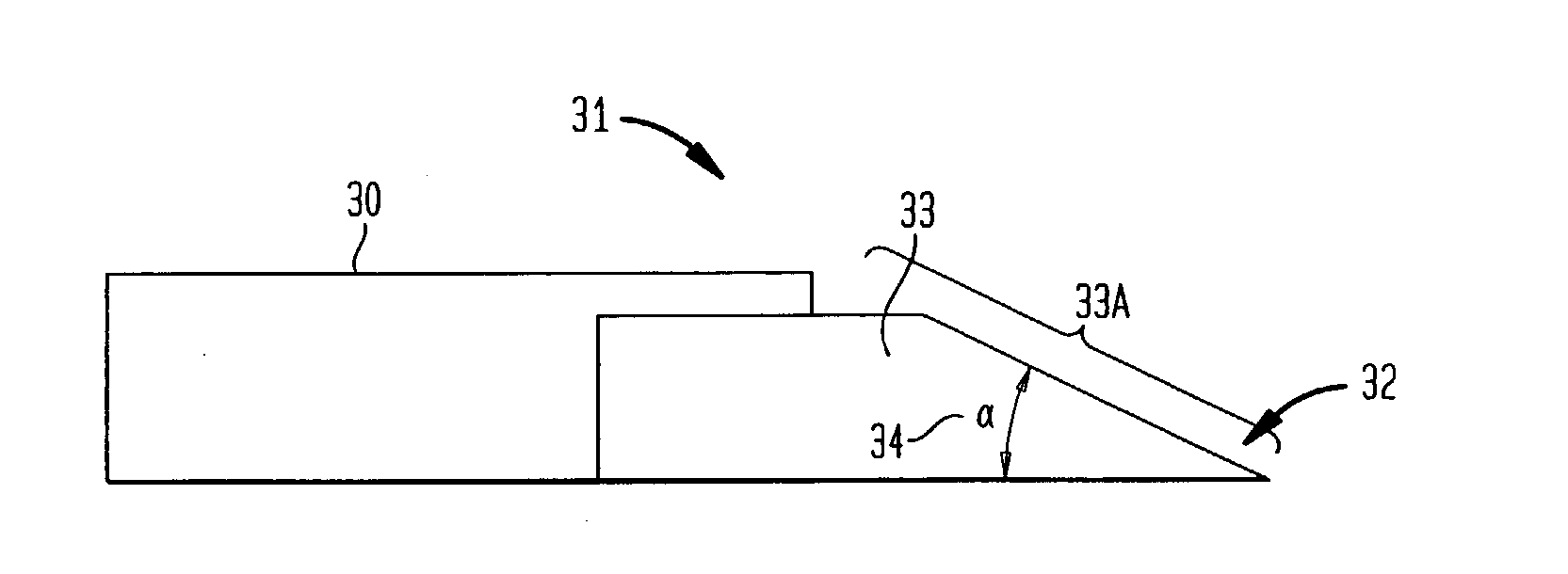
[0044] Referring initially to FIG. 5A, shown is a side view of a preferred embodiment of spray needle 31 according to the present invention. As shown, spray needle 31 according to the preferred embodiment of the invention comprises two com...


PUM


Abstract

The present invention relates to a spray needle for use in electrospray ionization (ESI) for mass spectrometry. A spray needle is disclosed which is constructed to have an opening along its length such that a sample solution may be more readily introduced or loaded therein. Further, the design of the spray needle of the invention is more durable than the prior art spray needles and may be reusable. Because sample loading is more readily achieved, the spray needle of the invention is appropriate for use with a fully automated system for the analysis of samples.

Description

[0001] The present invention relates generally to electrospray ionization for mass spectrometry, and more particularly the invention relates to an apparatus and method for producing an electrospray from a sample solution for introduction into mass spectrometer.BACKGROUND OF THE PRESENT INVENTION[0002] Mass spectrometry is an important tool in the analysis of a wide range of chemical compounds. Specifically, mass spectrometers can be used to determine the molecular weight of sample compounds. The analysis of samples by mass spectrometry consists of three main steps--formation of gas phase ions from sample material, mass analysis of the ions to separate the ions from one another according to ion mass, and detection of the ions. A variety of means exist in the field of mass spectrometry to perform each of these three functions. The particular combination of means used in a given spectrometer determine the characteristics of that spectrometer.[0003] The present invention relates to the ...

Claims


Application Information

Patent Timeline
Patent Type & Authority Applications(United States)
IPC IPC(8): H01J49/04
CPCH01J49/167
Inventor PARK, MELVIN A.
Owner BRUKER SCI LLC
Why Eureka
Try Eureka