Process and apparatus for the fractional distillation of crude oil

a fractional distillation and crude oil technology, applied in the combustion process, tar working up by chemical refining, contaminated soil reclamation, etc., can solve the problems of affecting plant throughput, significant amount of valuable low-boiling components remain trapped in viscous residue, and it is impossible to strip them from residu

Inactive Publication Date: 2004-01-22
VOMM CHEMIPHARMA
View PDF6 Cites 11 Cited by
  • Summary
  • Abstract
  • Description
  • Claims
  • Application Information

AI Technical Summary

Benefits of technology

[0011] The idea that led to the solution of the above problem was that of placing the crude oil to be fractionated in the most intimate contact possible with the stripping steam, in order to increase the yield in lightweight components and to reduce to a minimum the periodic stops for removing the residue from the column bottom.
[0028] It has been found experimentally that, by having the crude oil and steam intimately blended together within the turbomixer, a more effective distillation can be obtained, and this at a lower operating temperature. The lower temperature additionally minimizes any undesired cracking reactions.
[0029] By having the oil and steam instantly intimately contacted within the blend, a faster and more effective separation of the volatile components is promoted, and the amount of recycling required for proper fractionating is reduced.
[0030] Also, recycling the liquid phase collected from the column bottom allows those low-boiling components that, in conventional fractionating processes, remain trapped in the residue on the column bottom to be released in the utmost proportion.
[0031] An important advantage of the inventive process is that it can avoid, or at least minimize, the formation of dense viscous residue on the column bottom by virtue of the liquid on the column bottom being cycled continuously back into the turbomixer.
[0033] In this way, the need to have the column bottom cleaned periodically is eliminated, or at least greatly reduced, which, as said before, considerably depressed the refining plant throughput.

Problems solved by technology

Of course, stopping the refining process affects the plant throughput adversely.
Also, a significant amount of valuable low-boiling components remain trapped in the viscous residue, it being impossible to strip them from the residue by ordinary steam injection.

Method used


Image

  • Process and apparatus for the fractional distillation of crude oil

Examples


Embodiment Construction

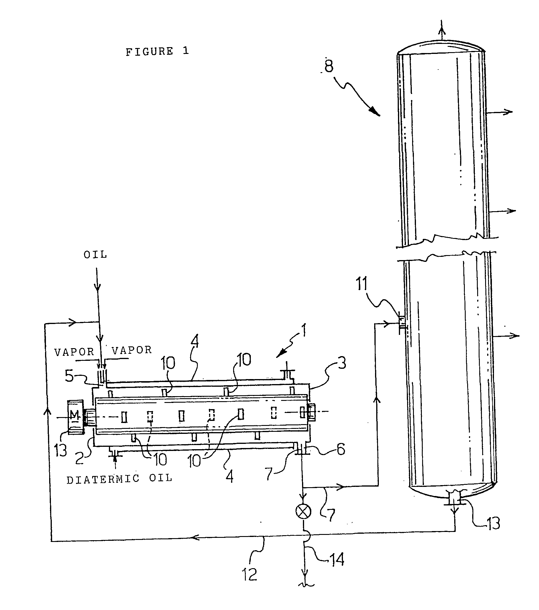
[0051] Using the apparatus summarized hereinabove in the process of this invention, crude oil from a preheating furnace at 350.degree. C. was fed continuously into turbomixer 1 at the rate of 1000 l / h, concurrently with and in the same direction as a steam current.

[0052] The wall temperature was maintained at about 350.degree. C., and the rotational velocity of the paddled rotor 9 constant at 30 m / s.

[0053] After an average 50 seconds of residence in the turbomixer, a current of steam, and vapor and liquid oil components, was continuously discharged and continuously fed into a fractionating column 8 under atmospheric pressure, at the level of an intermediate tray in the column.

[0054] Once a condition of equilibrium was attained for distillation, the usual fractions (gasoline, Diesel oil, kerosene, etc.) were withdrawn continuously at given levels, at the same time as the reflux rate was adjusted in conformity with ASTM Method D 2892. This Method provides for 14 to 17 theoretical tray...


PUM


Abstract

A process for the fractional distillation of crude oil, which comprises the steps of: feeding a continuous current of crude oil at 310-400° C. into a turbomixer comprising a tubular cylindrical body (1) provided with a rotor (9) formed with helically oriented paddles (10) and rotatably supported inside the body, along with a continuous current of steam; subjecting both currents to the mechanical action of the paddled rotor (9), so as to create a thin tubular dynamic turbulent layer, which is discharged and fed continuously into a fractioning column, at a predetermined height level in the column, to produce an upward-flowing vapor current and a downward-flowing liquid current therein; and optionally discharging the downward-flowing liquid current continuously from the column bottom, and feeding it continuously into the turbomixer in the same direction as the crude oil current.

Description

DESCRIPTIONFIELD OF APPLICATION[0001] The field of this invention is the petrochemical industry.[0002] In particular, the invention relates to a process and an apparatus for fractionating crude oil.PRIOR ART[0003] It is well known that to obtain suitable products for use as fuels, raw materials in the chemical industry, lubricants, etc., from crude oil, a number of processing steps are to be carried out, starting of necessity with the fractional distillation of the crude oil. This may be followed by other processes, among which reforming and cracking, for further purifying the products delivered from the fractionating process, improving their quality, or modifying them.[0004] The fractional distillation of crude oil is carried out, in large fractionating columns provided with perforated or bell-shaped trays, by feeding the crude oil, as preliminarily desalted and heated in a furnace to a temperature of 310.degree. to 400.degree. C., onto a tray located at an intermediate height leve...

Claims


Application Information

Patent Timeline
IPC IPC(8): B01D3/14C10G7/00
CPCC10G7/00B01D3/14
Inventor CEREA, GIUSEPPINA
Owner VOMM CHEMIPHARMA
Why Eureka
Try Eureka