
Microcell electrochemical devices and assemblies with corrosion-resistant current collectors, and method of making the same

a technology of current collectors and electrochemical devices, which is applied in the direction of cell components, final product manufacturing, sustainable manufacturing/processing, etc., can solve the problems of shortening the useful life, reducing the power density of microcell assemblies, and being exposed to harsh chemical environments

Inactive Publication Date: 2004-01-08
MICROCELL CORP
View PDF25 Cites 30 Cited by
  • Summary
  • Abstract
  • Description
  • Claims
  • Application Information

AI Technical Summary

Benefits of technology

[0019] Other aspects, features and advantages of the invention will be more fully apparent from the ensuing disclosure and appended claims.

Problems solved by technology

They therefore are subjected to a harsh chemical environment.
Since the current collectors of the microcells are formed of very thin metal fibers, they are especially susceptible to corrosion, which may result in electrical disconnection within individual microcells or between serially or parallelly connected microcells, eventually shortening the useful life and / or reducing the power density of the microcell assemblies.
Although the graphite or carbon-coated current collectors have significantly enhanced corrosion resistance in comparison with the conventional metal current collectors, they are not mechanically robust (i.e., the graphite current collectors are easily broken, and the carbon coating are easily peeled off, exposing the underlying metal core to the corrosive electrolyte), which will result in eventual electrical disconnection within or between the microcells.

Method used


Image

  • Microcell electrochemical devices and assemblies with corrosion-resistant current collectors, and method of making the same
  • Microcell electrochemical devices and assemblies with corrosion-resistant current collectors, and method of making the same
  • Microcell electrochemical devices and assemblies with corrosion-resistant current collectors, and method of making the same

Examples


Embodiment Construction

[0025] The disclosures of Eshraghi U.S. Pat. Nos. 5,916,514; 5,928,808; 5,989,300; 6,004,691; 6,338,913; and 6,399,232 hereby are incorporated herein by reference, in their respective entireties and for all purposes.

[0026] As used herein, the term "microcell" refers to an electrochemical cell energy generation or conversion structure, including a membrane separator having electrolyte embedded therein. The electrolyte material can be a solid ion-exchanging material evenly distributed within the membrane separator, or solid ion-exchanging particles immobilized in micropores of the membrane separator; alternatively, the membrane separator itself may be formed of ion-exchanging material that functions as electrolyte medium. The membrane separator is in contact with electrically conductive fibers, which in turn are in contact with or are coated with electrocatalyst and form positive and negative electrodes for the electrochemical cell.

[0027] While the ensuing description herein is primar...


PUM

PropertyMeasurementUnit
outer diameteraaaaaaaaaa

Abstract

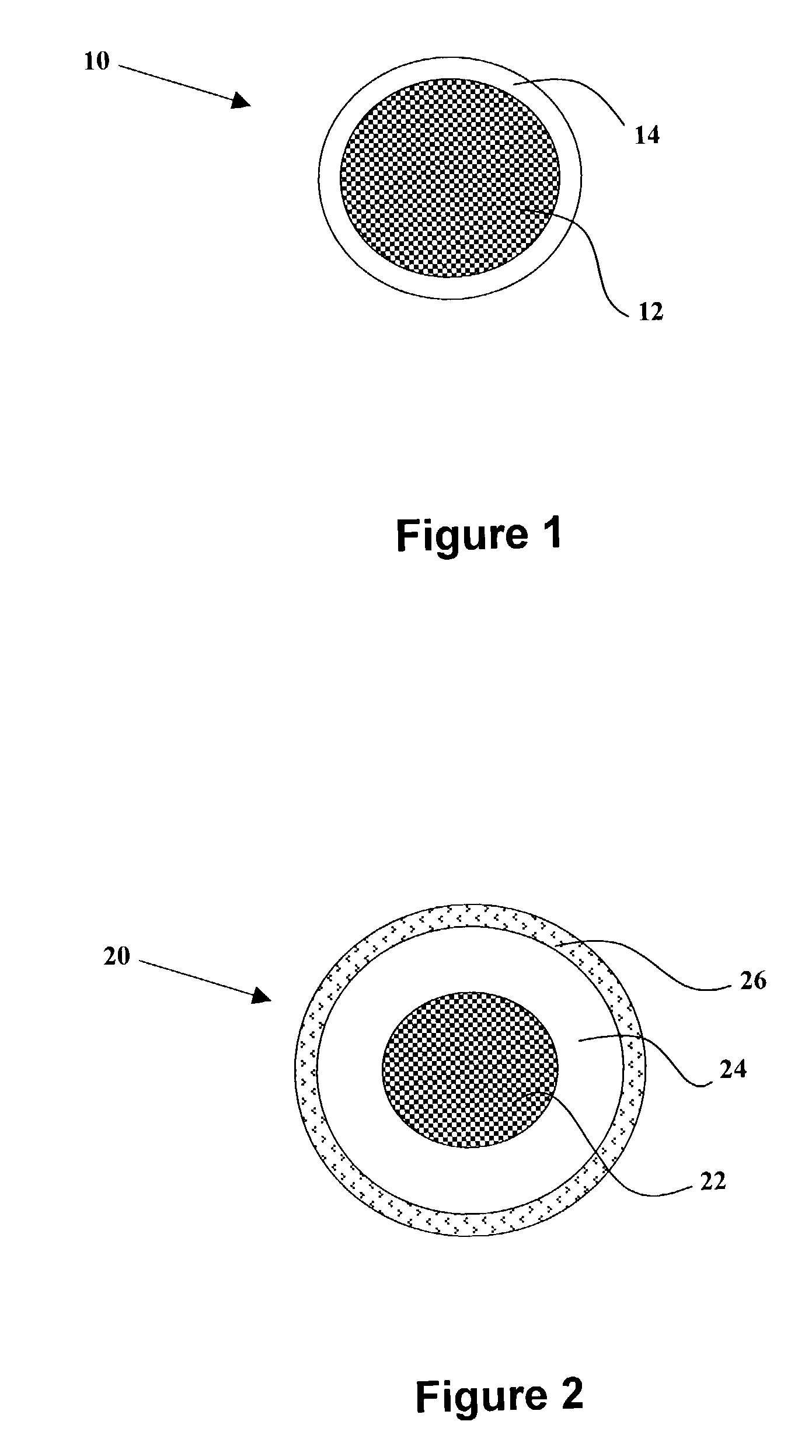
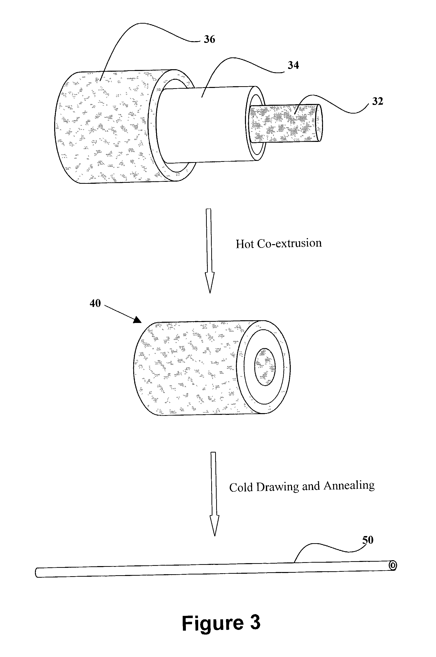
A fibrous microcell structure comprising: (1) an inner electrode, (2) a hollow fibrous membrane separator in contact with the inner electrode, (3) an electrolyte embedded in the hollow fibrous membrane separator, and (4) an outer electrode, wherein at least one of the inner and outer electrodes comprises a metal clad composite having two or more metal layers bonded together by solid-phase bonding. Preferably, such fibrous microcell structure is a fuel cell that comprises inner current collector, an inner catalyst layer, a hollow fibrous membrane separator in contact with the inner catalyst layer and the inner current collector, an electrolyte embedded in the hollow fibrous membrane separator, an outer catalyst layer, and an outer current collector.

Description

[0001] I. Field of the Invention[0002] This invention relates to microcell electrochemical devices and assemblies, and method of making the same. More specifically, this invention relates to microcell electrochemical devices and assemblies that comprise current collectors of high electrical conductivity, high corrosion resistance, and high mechanical endurance and resistance to peeling and wearing.[0003] II. Description of the Art[0004] Electrochemical cells, such as batteries and fuel cells, have positive and negative electrodes that are separated in such manner as to avoid internal short-circuiting, while the electrodes are in contact with an electrolyte medium, which chemically reacts with the electrodes to generate flow of electrons, thus providing electrical energy when the circuit is coupled with an external load.[0005] A recent innovation in the electrochemical energy field is the development of microcells--small-sized electrochemical cells for battery, fuel cell and other el...

Claims


Application Information

Patent Timeline
Patent Type & Authority Applications(United States)
IPC IPC(8): B32B15/01B32B15/02H01M2/16H01M2/18H01M4/02H01M4/38H01M4/46H01M4/66H01M4/86H01M4/88H01M4/90H01M8/02H01M8/04H01M8/10H01M10/04H01M10/14H01M10/39
CPCH01M2/162H01M4/38H01M4/46H01M4/661H01M4/8605Y10T29/49108H01M8/1002H01M10/39Y02E60/521Y10T29/49115Y10T29/10H01M4/90H01M8/1007Y02P70/50Y02E60/50Y02E60/10H01M50/44
Inventor ESHRAGHI, RAY R.
Owner MICROCELL CORP
Learn More