Eureka AIR delivers breakthrough ideas for toughest innovation challenges, trusted by R&D personnel around the world.

Electroluminescent devices

a technology of electroluminescent devices and electrodes, applied in the direction of discharge tube luminescnet screens, organic semiconductor devices, natural mineral layered products, etc., to achieve the effect of long operation stability and high fluorescent intensity

Inactive Publication Date: 2003-11-20
ELIGHT
View PDF0 Cites 97 Cited by
  • Summary
  • Abstract
  • Description
  • Claims
  • Application Information

AI Technical Summary

Benefits of technology

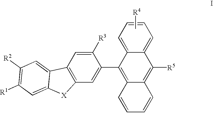
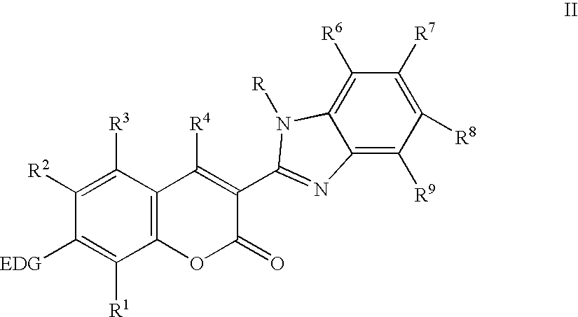
[0037] It is an advantage of the present invention, that the organic electroluminescent (EL) element, which belongs to anthracene, coumarine and benazole derivatives, or their combinations, provides thermally stable, glassy, and highly fluorescent materials in condensed thin films. As a result, organic EL devices employing certain of these derivatives in the light-emitting layer can produce full range of emission spectra and long operational stability.
[0038] In drawings, which illustrate specific embodiments of the invention, but which, should not be construed as restricting the spirit or scope of the invention in any way:

Problems solved by technology

However, these devices require excitation voltages on the order of 100 volts or greater.

Method used


Image

  • Electroluminescent devices
  • Electroluminescent devices
  • Electroluminescent devices

Examples


example 1

Synthesis of 9,9-Diethylfluorene

[0103] To a mechanically stirred mixture of fluorine (83.2 g. 0.5 mol.), powdered potassium hydroxide (140 g., 2.5 mol.), potassium iodide (4.0 g., 0.024 mol.) and DMSO (225 ml), cooled to 15-20.degree. C., bromoethane (104 ml., 151.84 g., 1.39 mol.) was added over a period of 1.5 hours, and allowed to stir at room temperature overnight. The mixture was diluted with water (1200 ml), and extracted with toluene (2.times.400 ml). The toluene extract was washed with water, dried and concentrated to get 116.66 g., of a red oil. This was distilled at 1.2 mm, b.p. 125.degree. C. to get a colorless oil, that solidified, 104.32 g., (94% yield).

example 2

Synthesis of 2-Bromo-9,9-diethylfluorene

[0104] To a solution of diethylfluorene (22.2 g., 0.1 mol.) in propylene carbonate (100 ml), N-bromosuccinimide (17.8 g., 0.1 mol.) was added at 57.degree. C. in portions and the mixture was stirred for 30 minutes at 60.degree. C. The mixture was diluted with 1200 ml of water and extracted with 500 ml of toluene. The toluene extract was washed 3 times with 300 ml portions of water, dried and concentrated. The crude product from 3 batches of the same size totaled 117 g. oil. This was distilled at 2 mm. The first fraction, b.p. 90-93.degree. C., 22.33 g., was found to be propylene carbonate. The second fraction, b. p. 155-165.degree. C., 81.0 g. (89.7% yield), was the desired compound.

example 3

Synthesis of 9,9-diethylfluorenyl-2-boronic Acid

[0105] A solution of n-BuLi (1.6 M in hexane, 100 mL, 0.16 mol) was added via an addition funnel to 2-bromo-9,9-diethylfluorene prepared by example 2 (42.0 g, 0.14 mol) in 200 mL of dry THF at -78 C. The yellow suspension was stirred at this temperature for a half hour, a solution of B(OMe).sub.3 (26.6 mL, 29.1 g, 0.28 mol) in 150 mL of dry THF was added dropwise, with the temperature kept below -60.degree. C. The resulting colorless solution was allowed to warm to room temperature 2 hour, then 300 mL of 5 M HCl was added and the mixture stirred for a further one hour under nitrogen. Water and ether were added, and the aqueous layer was extracted several times with ether. The combined organic extracts were dried over MgSO4 and evaporated under reduced pressure to yield a white solid (34.0 g, 95%), which was used in the coupling reaction without further purification.


PUM

PropertyMeasurementUnit
excitation voltagesaaaaaaaaaa
thicknessaaaaaaaaaa
thicknessaaaaaaaaaa

Abstract

This invention relates to compositions and electroluminescent (EL) devices that have enhanced performance as a result of a novel class of anthracene derivatives used as host materials for a full range of color dopands. When using coumarin derivatives as color dopands in the anthracene derivatives in an EL device, the device performs a desirable light emitting efficiency and durability. The performance of the EL device can be further improved by using benazole derivatives as the electron transporting layer. The organic EL device of the present invention is useful in preparing display devices.

Description

[0001] This invention relates to novel electroluminescent devices with enhanced performance, and which devices are desired that are capable of providing uniform luminescence with full visible spectra, high electroluminescent efficiency, excellent durability, and low driving voltages.[0002] Organic electroluminescent (EL) devices are generally composed of a single or multiple layers of organic materials sandwiched between transparent and metallic electrodes. Organic EL devices are attractive owing to the requirement for low driving voltage and the fact that they are generally simple and relatively easy and inexpensive to fabricate. Furthermore, the light generated by organic EL devices is sufficient for use in a variety of ambient light conditions (from little or no ambient light to bright ambient light). There has been an increased interest in developing energy-efficient flat-panel displays based on organic EL devices primarily because of their potential as an emissive display techn...

Claims


Application Information

Patent Timeline
Patent Type & Authority Applications(United States)
IPC IPC(8): C07D209/10C07D209/86C07D209/88C07D235/20C07D263/56C07D263/57C07D277/66C07D405/04C07D405/14C09K11/06H10K99/00
CPCC07D209/10H01L2251/308C07D209/88C07D235/20C07D263/57C07D277/66C07D405/04C07D405/14C09K11/06C09K2211/1011C09K2211/1029C09K2211/1044C09K2211/1048C09K2211/1051C09K2211/1074H01L51/0052H01L51/0054H01L51/0055H01L51/0058H01L51/0059H01L51/006H01L51/0064H01L51/0072H01L51/0073H01L51/0081C07D209/86H10K85/623H10K85/652H10K85/622H10K85/615H10K85/631H10K85/626H10K85/633H10K85/6574H10K85/6572H10K85/324H10K2102/103
Inventor XIE, SHUANG
Owner ELIGHT
Why Eureka
Eureka Blog
Learn More