
Noise attenuating emission converter

a technology of noise attenuation converter and emission converter, which is applied in the direction of machines/engines, filtration separation, separation processes, etc., can solve the problems of significant cost of separate units for noise attenuation and chemical gas conversion, and the effect of not effectively reducing or attenuating the frequency of the frequency

Inactive Publication Date: 2003-11-13
RAO V DURGA NAWAR +2
View PDF6 Cites 22 Cited by
  • Summary
  • Abstract
  • Description
  • Claims
  • Application Information

AI Technical Summary

Benefits of technology

[0006] Yet another object of this invention is to provide a device in conformity with the above object which has less back pressure while accomplishing such object, thus allowing the engine, to which it is connected, to operate with greater responsiveness.
[0008] Preferably, the pellets have one or more of the following: a hollow interior with pellet wall pores sized and arranged to communicate with the pellet interior to enhance noise attenuation; a pellet shape that is irregular but sized to closely fit the hydraulic diameter of the cross sectional area of the channels; the pellets are constituted of etched gamma alumina to eliminate the need for an adhering washcoat between said dolomitic carbonate / catalyzing material and the pellet. The device may advantageously use additional ceramic foam filters to trap significant soot separate from the substrate and provide augmentation of NO.sub.x conversion as well as better sound attenuation.

Problems solved by technology

Low frequency vibrations of the exhaust gases have a wave length as long as or considerably longer than the length of such substrate channels; such frequencies are not effectively damped or attenuated.
Unfortunately, the cost of separate units for noise attenuation and chemical gas conversion is significant.

Method used


Image

  • Noise attenuating emission converter
  • Noise attenuating emission converter
  • Noise attenuating emission converter

Examples


Embodiment Construction

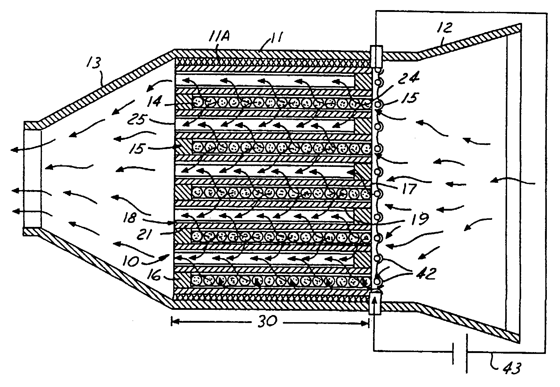
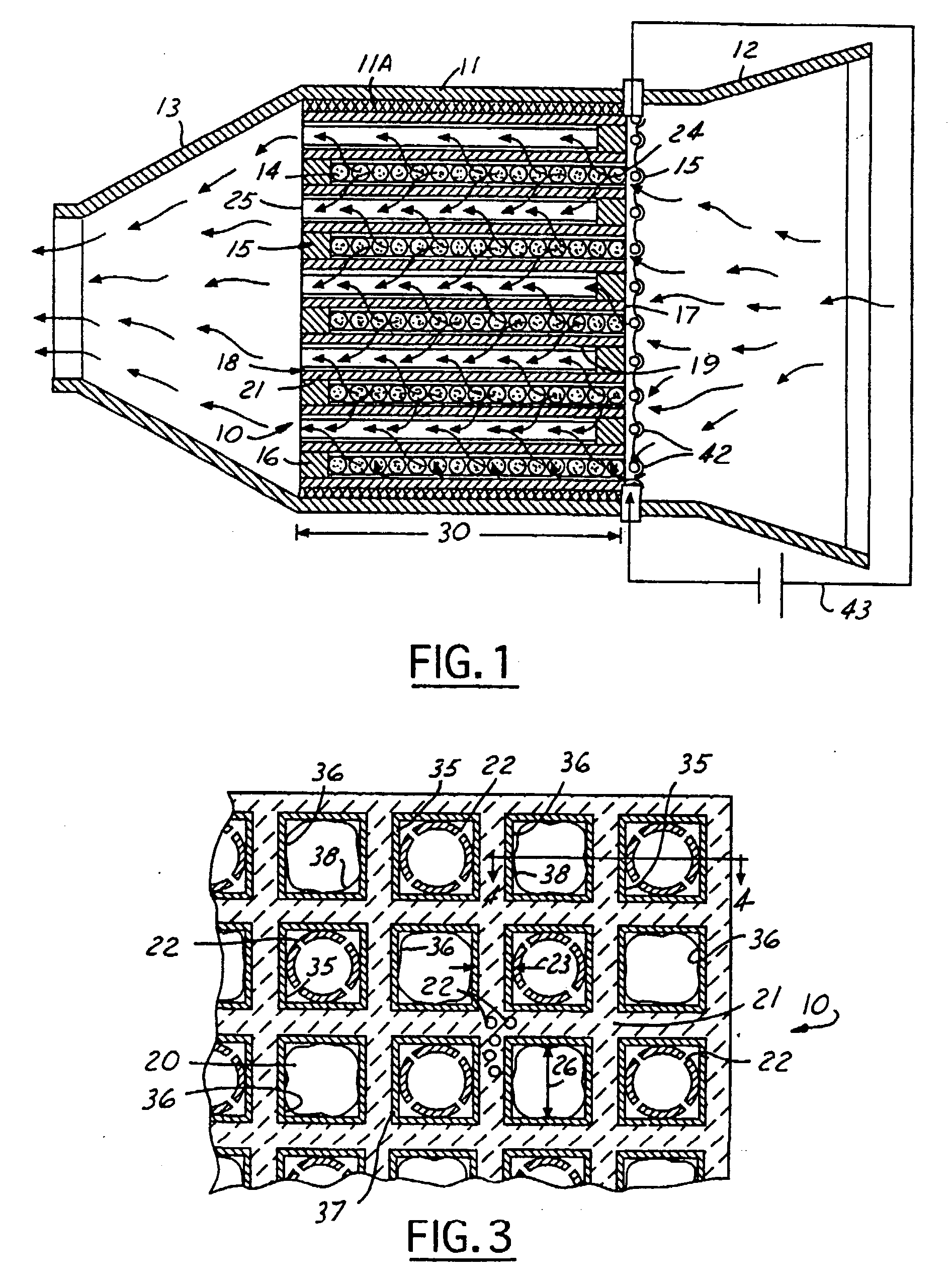
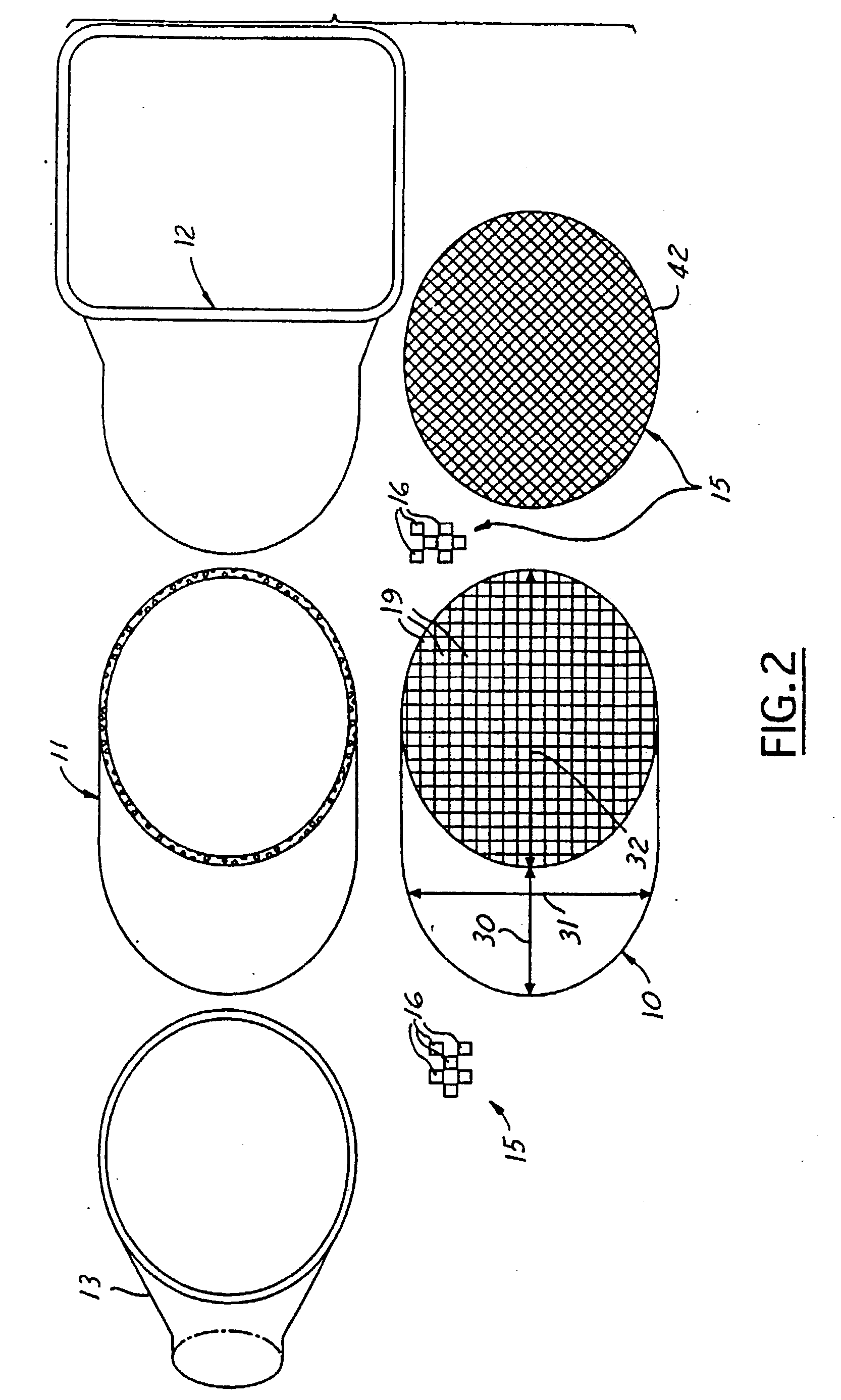
[0017] The device of this invention functions simultaneously to attenuate exhaust gas noise and to more effectively convert the noxious elements of the exhaust gases to harmless elements particularly from a lean burn gasoline engine or diesel engine. The embodiment of FIGS. 1-2 is comprised of the following principal elements: a multi-channeled substrate 10, canister 11 (carrying a Fibrefrax interior cushioning layer 11A) for supporting the substrate, inlet and outlet flow guides 12, 13, respectively, micro-sized pellets 14 filling at least certain of the substrate channels, and structural means 15 for trapping the pellets in the channels.

[0018] The substrate 10, as shown in FIGS. 1-3, comprises a high temperature ceramic monolith body constituted preferably of ceramic corderite [Mg Al.sub.2O.sub.3 (SiO.sub.2).sub.4] which has a minimum melting temperature of about 2250.degree. F. The substrate 10 has parallel aligned inlet (frontal) face 17 and exit (trailing) face 18 between which...


PUM

PropertyMeasurementUnit
Pore sizeaaaaaaaaaa
Pore sizeaaaaaaaaaa
Thicknessaaaaaaaaaa

Abstract

An automotive exhaust gas noise attenuating device which treats exhaust gas emissions, the device having (a) a ceramic substrate for passing an automotive exhaust stream therethrough, the substrate having (i) an inlet face and an outlet face with a plurality of aligned thin porous channel walls defining channels extending between the faces, and (ii) a three dimensional aspect relationship where depth of the substrate between said faces is generally the same as either the height of width of a face, the substrate having first alternates of the channels blocked at the outlet face and second alternates of the channels blocked at the inlet face to promote lateral flow through the porous walls between each first channel and a multiple of second alternate channels while permitting laminar flow within such channels; (b) hollow shell pellets packed into and trapped in at least some of the first alternate channels which cooperate to define porous Darcy flow surfaces therein; and (c) dolomitic carbonate and catalyzing material on or in the surfaces of the channel walls and Darcy flow surfaces.

Description

[0001] This invention relates to the technology of suppressing noise from the exhaust gases emitted from an automotive internal combustion engine, and more broadly to the technical field of emission converters which are placed in the automotive exhaust stream along with separate noise mufflers to convert the chemically noxious elements of such exhaust.DISCUSSION OF THE PRIOR ART[0002] Conventional contemporary automotive exhaust gas converters employ a porous ceramic substrate with a plurality of parallel aligned channels extending between an inlet (front) face and an exit (back) face of the substrate. Although the channels allow the exhaust stream to flow straight through the substrate, the channel cross-sections are sufficiently small to permit some degree of gas particle reactions at the surface of the channel walls so that coatings on the channel walls can promote chemical catalysis and thereby oxidation or reduction of the noxious elements. However, the exhaust flow remains ess...

Claims


Application Information

Patent Timeline
IPC IPC(8): B01D39/14B01D39/20B01D53/94F01N1/00F01N1/08F01N3/02F01N3/24F01N3/28
CPCF01N1/082F01N3/2892F01N3/2885F01N3/2828Y02A50/20
Inventor RAO, V. DURGA NAGESWARCIKANEK, HARRY ARTHURWATKINS, WILLIAM LEWIS HENDERSON
Owner RAO V DURGA NAWAR
Learn More