Aerodynamic catalytic converter

a catalytic converter and aerodynamic technology, applied in the field of catalytic converters, can solve the problems of increasing the weight of the catalytic converter, reducing clogging the catalytic converter, so as to improve the efficiency of the engine, reduce the weight, and reduce the friction of the gas flow

Active Publication Date: 2020-01-02
JAN JONATHAN +1
View PDF7 Cites 0 Cited by
  • Summary
  • Abstract
  • Description
  • Claims
  • Application Information

AI Technical Summary

Benefits of technology

[0009]Firstly, the core of the improved catalytic converter is made of a three-dimensional reticulated ceramic structure. For the same volume of the core, reticulated ceramic has approximately four times the surface area of honeycomb ceramics. And there is less friction of gas flow. This is commonly referred to as laminar flow, meaning that gas flows along the surface of the ceramic. Less back-pressure improves the engine efficiency. The ceramic is made from a clay formula where ceramic bubbles are incorporated not only to reduce the weight, but also to improve the structural strength. Less heat is accumulated in the lightweight ceramic thereby minimizing overheating and fire hazard. Mica flakes may also be included in the clay. This can increase the refractive index, thus more heat can be irradiated away from the ceramic material. Catalytic reduction process is more efficient at lower temperature.
[0010]Secondly, a Coanda effect chamber is installed between the exhaust pipe and the inlet of the catalytic converter. Fresh air is introduced into the Coanda chamber via aspiration. Fresh air is decelerated then accelerated when mixed with exhaust gas in the Coanda chamber. This lower-temperature higher-volume gas has more oxygen supply that enhances the oxidation process by the catalysts. It also reduces NOx, a volatile product from high operating temperature in the combustion chamber, back into stable state of nitrogen molecules.

Problems solved by technology

Due to the restriction of gas flow through the catalytic converter, excessive backpressure compromises the engine's efficiency.
Fire hazards and clogged catalytic converters are common.
Gas flow is more efficient through the honeycomb, but overheating and clogging are still inevitable issues.
Eventually the DPF is clogged and requires replacement.
Damages to the engine is also inevitable Fleet operators have experienced substantial downtime and increased maintenance costs.
There have been numerous incidents that diesel cars flaring up in parking structures.
When urea leaks into the exhaust system, it blows up upon encountering hot catalytic converter elements.
Against engineering common sense, the injected air causes high backpressure, choking the engine.
And pump failure is inevitable.
Firstly, the core of the improved catalytic converter is made of a three-dimensional reticulated ceramic structure. For the same volume of the core, reticulated ceramic has approximately four times the surface area of honeycomb ceramics. And there is less friction of gas flow. This is commonly referred to as laminar flow, meaning that gas flows along the surface of the ceramic. Less back-pressure improves the engine efficiency. The ceramic is made from a clay formula where ceramic bubbles are incorporated not only to reduce the weight, but also to improve the structural strength. Less heat is accumulated in the lightweight ceramic thereby minimizing overheating and fire hazard. Mica flakes may also be included in the clay. This can increase the refractive index, thus more heat can be irradiated away from the ceramic material. Catalytic reduction process is more efficient at lower temperature.
Secondly, a Coanda effect chamber is installed between the exhaust pipe and the inlet of the catalytic converter. Fresh air is introduced into the Coanda chamber via aspiration. Fresh air is decelerated then accelerated when mixed with exhaust gas in the Coanda chamber. This lower-temperature higher-volume gas has more oxygen supply that enhances the oxidation process by the catalysts. It also reduces NOx, a volatile product from high operating temperature in the combustion chamber, back into stable state of nitrogen molecules.

Method used


Image

  • Aerodynamic catalytic converter
  • Aerodynamic catalytic converter
  • Aerodynamic catalytic converter

Examples


Embodiment Construction

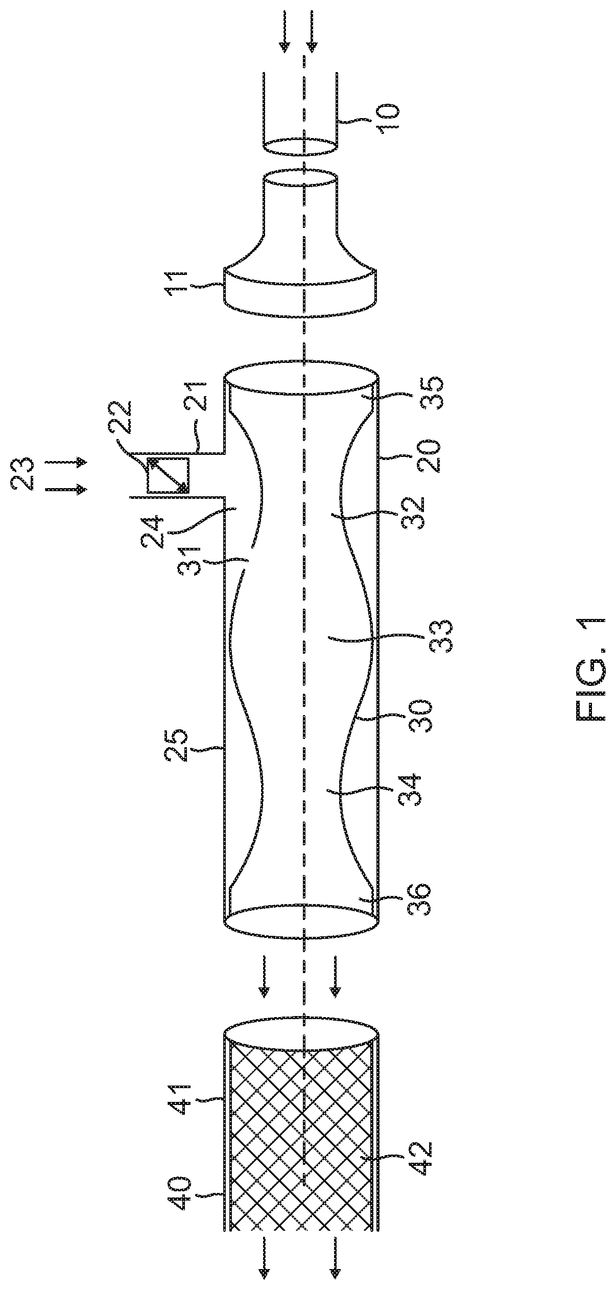
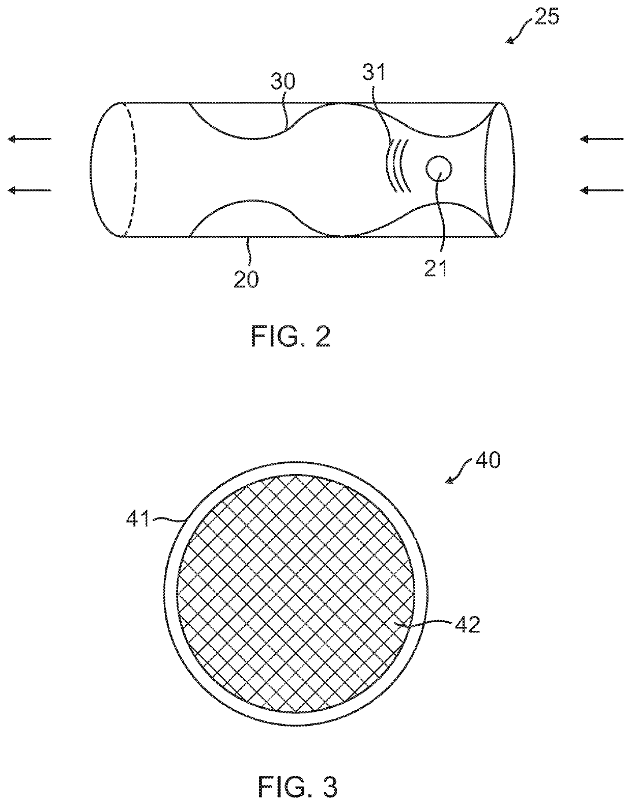
[0025]FIG. 1 is a cross-sectional view of the catalytic converter according to an embodiment of the present invention, in a plane passing through its longitudinal axis of the catalytic converter. The catalytic converter includes a Coanda chamber assembly 25 and a catalytic reaction chamber 40. The Coanda chamber assembly 25 is coupled at its distal (downstream) end to the catalytic reaction chamber 40 and at its proximate (upstream) end to an exhaust pipe 10. The interior space (the Coanda chamber), as defined by an interior housing 30, is rotationally symmetrical around the longitudinal axis and has varying diameters, including at least a first narrower section 32 (the most upstream narrower section) and a first wider section 33 immediately downstream of the first narrow section. Preferably, the diameter at the widest point of the first wider section 33 is 2 to 3 times the diameter at the narrowest point of the first narrower section 32. In the illustrated embodiment, the interior ...


PUM


Abstract

An improved catalytic converter includes a Coanda chamber assembly connected upstream of a catalytic reaction chamber, where the exhaust pipe is to be connected to the Coanda chamber assembly. The Coanda chamber assembly forms a Coanda chamber that has at least one narrower section and at least one wider section immediately downstream of the narrower section, with openings formed at the narrowest point of a narrower section. In operation, when engine exhaust gas is fed into the Coanda chamber, the gas pressure increases at the narrower section, and drops when the gas enters the wider section. As a result, air is sucked into the Coanda chamber via the openings and mixes with the exhaust gas. This lowers the exhaust temperature and enhances the efficiency of the catalytic reactions in the catalytic reaction chamber.

Description

BACKGROUND OF THE INVENTIONField of the Invention[0001]This invention relates to a catalytic converter.Description of Related Art[0002]Catalytic converters have been widely used in the past 40 years as a means to minimize exhaust gas pollutants for internal combustion engines.[0003]First generation catalytic converters are made up of ceramic beads coated with noble metal oxide catalysts that are packed inside a steel tube that is attached to the engine exhaust pipe. Ceramic is a refractory material that accumulates heat. The un-burnt hydrocarbon in the exhaust gas is oxidized by the catalysts in the chamber. Due to the restriction of gas flow through the catalytic converter, excessive backpressure compromises the engine's efficiency. The loosely packed ceramic beads also accumulate heat as well as solid particulate deposit. Fire hazards and clogged catalytic converters are common.[0004]Second generation catalytic converters use honeycomb ceramic structure which is coated with cataly...

Claims


Application Information

Patent Timeline
Patent Type & Authority Applications(United States)
IPC IPC(8): F01N3/28B01D53/94F01N3/34F01N3/08
CPCF01N3/2892F01N3/34B01D53/9454F01N3/0892F01N3/2825F01N3/2882F01N2370/02F01N2510/06F01N2330/06F01N3/10F01N3/2828F01N2470/30Y02T10/12
Inventor JAN, JONATHANSNAPER, ALVIN A.
Owner JAN JONATHAN
Why Eureka
Try Eureka