
Miniature ion mobility spectrometer

Inactive Publication Date: 2003-08-21
RAYTHEON CO
View PDF0 Cites 27 Cited by
  • Summary
  • Abstract
  • Description
  • Claims
  • Application Information

AI Technical Summary

Benefits of technology

[0009] The ion mobility spectrometer of the invention is more sensitive and has higher selectivity than prior devices operating according to the principle of ion mobility spectrometry. Due to the higher sensitivity of its physical structure and the electronics, the ion mobility spectrometer of the invention may operate using lower air flow rates and has a longer operating life on a smaller single set of batteries prior to recharging or replacement. The ion mobility spectrometer may therefore be readily carried in a hand or a pocket of the user. It may be powered by a conventional battery pack commonly used for personal-sized, hand-held instruments, such as a BA5800 / U battery pack issued by the US Government. Additionally, the analysis of chemical species is more precise than possible with existing ion mobility spectrometer devices, because larger numbers of sensing elements and two-dimensional arrays of sensing elements may be incorporated.
[0018] The sensor electrode array may be separate from the readout chip, or may be an integral part of it. The use of an integrated electrode and readout circuit allows the sensor electrodes to be made much smaller than previously possible in devices of this type. The use of smaller sensor electrodes leads to much higher spatial resolution of the mass distribution. Different types of sensor electrode arrays may be used, so that multiple types of data may be gathered. Additionally, the smaller sensor electrodes allow the gas flow rate to be reduced, reducing the amount of air that must be drawn through the gas flow channel and heated, and therefore the power requirements of the device. This, in turn, allows the gas flow channel to be smaller in cross section than previously possible. The use of the smaller sensor electrodes also allows the use of a two-dimensional array of sensor electrodes within the gas flow channel without enlarging the size of the cell. A two-dimensional array of sensor electrodes may be used to gather more information about the ionized species in the gas flow than can a one-dimensional array.
[0019] Accordingly, the miniaturization of the sensor elements is advantageous both in improving the portability of the ion mobility spectrometer and achieving a personal-sized device, and also in improving its data-gathering ability. Other features and advantages of the present invention will be apparent from the following more detailed description of the preferred embodiment, taken in conjunction with the accompanying drawings, which illustrate, by way of example, the principles of the invention. The scope of the invention is not, however, limited to this preferred embodiment.

Problems solved by technology

A person may be exposed to small amounts of species, such as organic agents, that may be quite harmful to the person's health.
For example, a soldier may be exposed to chemical warfare agents, a chemical worker may be exposed to leakages or spills, or a rescue worker may enter a situation where unknown chemical agents, some of which may be harmful, may be present.
However, many species either cause no such reactions, or cause harm even when present in concentrations below the human detection level.
The M-90 instrument has only two sets (channels) of three electrodes each, limiting the possible chemical resolution of the instrument.
Large air flow rates (up to 2 liters per minute) are used, requiring large power consumption to heat the air and force it through the flow channel.
The M-90 ion mobility spectrometer has a relatively high power consumption, requiring a large, bulky battery pack when used in the self-contained mode.
The existing devices cannot meet this requirement.
Other types of gas flow analysis devices that meet these requirements do not have the operating advantages of the ion mobility spectrometer.

Method used


Image

  • Miniature ion mobility spectrometer
  • Miniature ion mobility spectrometer
  • Miniature ion mobility spectrometer

Examples


Embodiment Construction

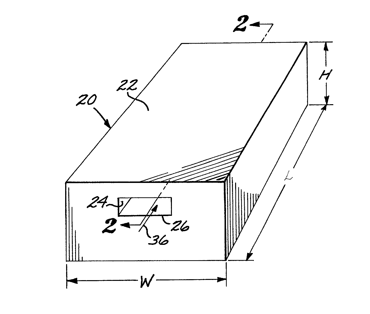
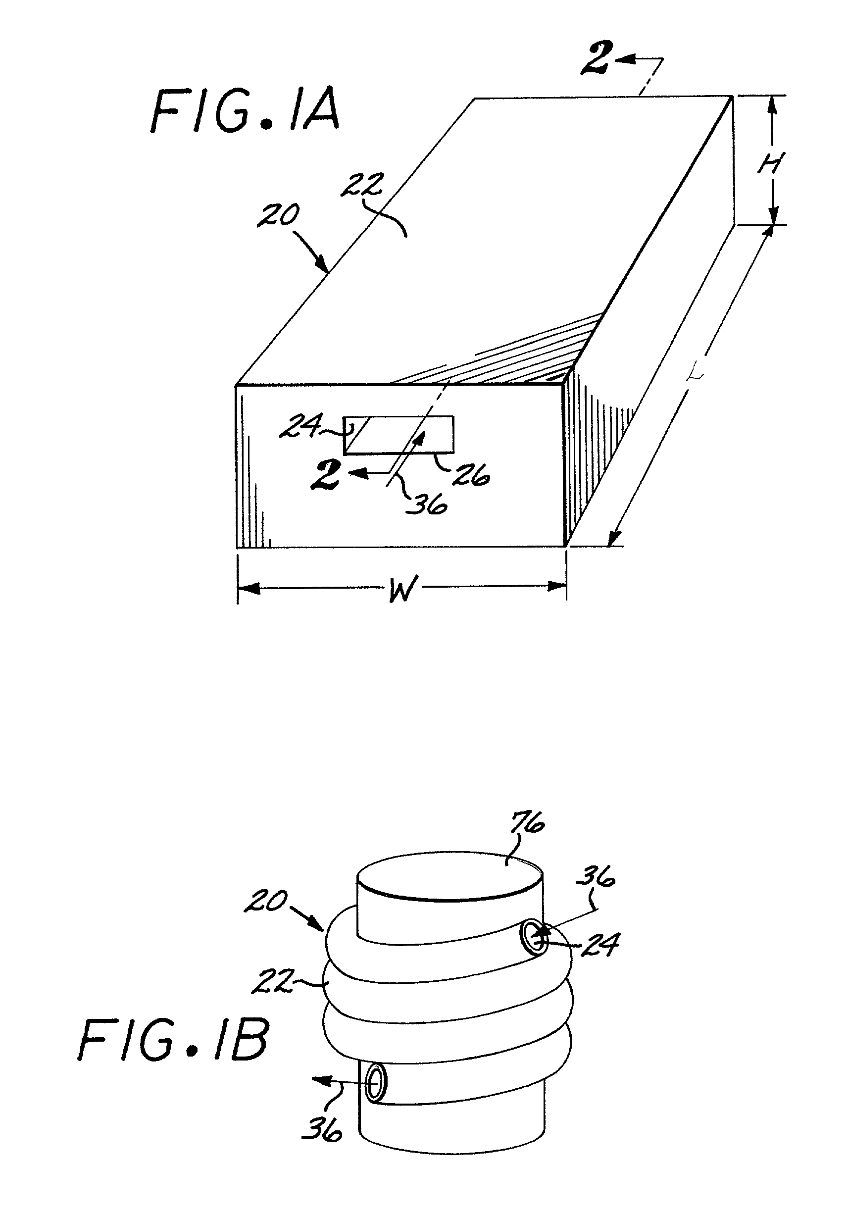
[0028] FIG. 1 is a perspective schematic view of an ion mobility spectrometer 20 according to the present invention. The ion mobility spectrometer 20 includes a housing 22 having a gas flow channel 24 therethrough. In the view of FIG. 1, a gas flow inlet 26 of the gas flow channel 24 may be seen. The overall dimensions of the ion mobility spectrometer 20 are a width W of about 3 inches, a length L of about 6 inches, and a height H of about 2 inches. The ion mobility spectrometer 20 of FIG. 1 weighs about 2 pounds, including its battery power source.

[0029] The small size of the ion mobility spectrometer 20 is conducive to its use in other, less conventional shapes. FIG. 1B illustrates the ion mobility spectrometer 20 having a flexible housing 22 wrapped around its battery.

[0030] FIGS. 2A-2B schematically illustrates the interior structure of the ion mobility spectrometer 20. FIG. 2A shows the ion mobility spectrometer 20 in a form having a straight, linear gas flow channel 24. FIG. 2...


PUM


Abstract

An ion mobility spectrometer includes a housing with a flow channel, an air pump to force air through the flow channel, a heater at an inlet end of the flow channel, and an ionization source that ionizes the air after it is heated. The heated, ionized air passes through an electric field produced by a field source and a plurality of sensor elements located within in the wall of the flow channel in the measurement region of the electric field. The sensor elements include a plurality of sensor electrodes in one wall of the flow channel. Ion currents to the sensor electrodes are measured by an integrated high-sensitivity readout circuit array, permitting the sensor electrodes to be quite small. The sensor electrodes may be arranged in one-dimensional or two-dimensional arrays.

Description

BACKGROUND OF THE INVENTION[0001] This invention relates to the measurement and identification of species in a flowing gas sample, and, more particularly, to a miniature device for performing such determinations.[0002] A person may be exposed to small amounts of species, such as organic agents, that may be quite harmful to the person's health. For example, a soldier may be exposed to chemical warfare agents, a chemical worker may be exposed to leakages or spills, or a rescue worker may enter a situation where unknown chemical agents, some of which may be harmful, may be present. In each such situation, it is important to know whether any such species are present and, if so, the nature of the species so that the person may take the necessary precautions.[0003] Where the concentrations of the species are relatively large, they may often be detected by the senses of the person, such as a characteristic smell, or a physiological reaction of the person, such as watering eyes. However, ma...

Claims


Application Information

Patent Timeline
IPC IPC(8): H01J49/28
CPCG01N27/622
Inventor MURPHY, J. BRIANMEGERLE, CLIFFORD A.TOWNSEND, CARL W.
Owner RAYTHEON CO
Learn More