
Injection mold for semi-solidified Fe alloy

a technology of injection molds and alloys, which is applied in the direction of metal-working apparatus, metal-working molds, metallic material coating processes, etc., can solve the problems of premature crack formation in the mold, shorten the mold life, and poor thermal conductivity of iron or steel materials inclusive of skd61

Inactive Publication Date: 2003-02-06
HONDA MOTOR CO LTD +1
View PDF2 Cites 21 Cited by
  • Summary
  • Abstract
  • Description
  • Claims
  • Application Information

AI Technical Summary

Benefits of technology

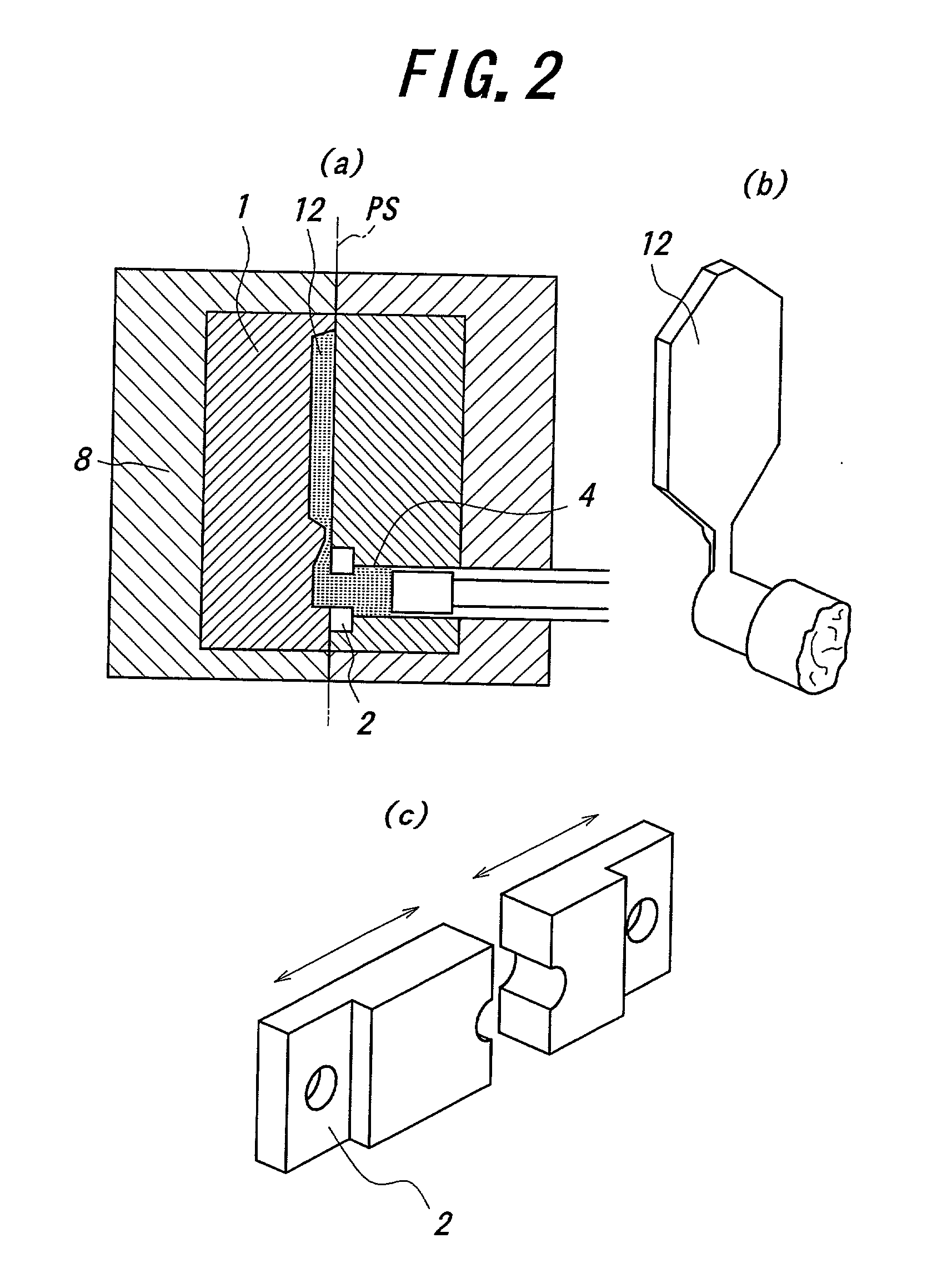
[0011] It is more specific object of the present invention to provide an improved injection mold for casting semi-solidified Fe alloy, having excellent thermal conductivity and mechanical strength, and capable of effectively preventing entry of surface oxide film of the semi-solidified Fe alloy into the mold cavity.
[0014] The inventors also found it effective to provide a scalping gate adjacent to the runner in communication with the mold cavity, and design the scalping gate to have an opening diameter slightly smaller than that of the pressure chamber, so as to positively eliminate surface oxide film of the semi-solidified Fe alloy as it is pressurized in the chamber and injected into the mold cavity.
[0018] The inventors then thoroughly conducted experiments and investigations on measures effectively allowing formation of a stable cermet coating that can be maintained in firm adhesion to the base material and exhibiting excellent durability against high thermal shock upon injection molding of semi-solidified Fe alloy, to thereby provide an improved injection mold suitable for practical injection-molding of the semi-solidified Fe alloy. The present invention is based on a novel recognition that the stability of the cermet coating and, hence, the durability of the injection mold can be advantageously improved by applying a pre-coating of Ni alloy as an intermediate layer, before applying a cermet coating on the base material.

Problems solved by technology

As generally known in the art, however, iron or steel materials inclusive of SKD61 have a poor thermal conductivity of typically 40 W / (m.multidot.K) or less.
Thus, when such materials are applied to an injection mold for casting metal, beside insufficient cooling capacity for the cast products or relatively long preheating time required for the mold, the following problems are likely to occur.
A) During gradual cooling and solidification of semi-solidified metal in the mold cavity, slurry tends to enter into clearances between knockout pins and surrounding holes, both provided for the mold, thereby forming undesirable flashes on the outer surface of the cast product, which must be removed to realize satisfactory product quality.
B) Plastic strains are accumulated in the mold due to large temperature gradient in the mold and repeated action of tensile and compressive stresses at the mold surface, and tend to cause premature crack formation in the mold.
Moreover, severe stress concentration occurs at convex surface portions of the mold cavity having a small radius of curvature, so that hair cracks tend to be formed in the mold surface to shorten the life of the mold.
C) In the case of semi-solidified Fe alloy which comprises hypo-eutectic cast iron, for example, the poor cooling capacity of the mold leads to coarse graphite structure after annealing.
In other words, it is difficult to obtain the desired fine graphite structure and sufficient mechanical strength of the cast products.
First of all, copper alloys had been generally considered to be unsuitable as casting molds for high temperature materials, because copper alloy has strength inferior to iron or steel materials, despite higher thermal conductivity.
As a result, it was found that considerable wear occurs at convex surface portions of the mold having a small radius of curvature near the opening of the scalping gate and within the mold cavity, indicating that the mold and the scalping gate require further improvement in terms of their durability for practical use.
However, even by applying a cermet coating to the copper alloy base materials, it was found that the cermet coating tends to be peeled off during the actual injection molding, making it still difficult to achieve the desired durability of the mold and scalping gate.
Copper alloy with a thermal conductivity less than 120 W / (m.multidot.K) does not provide a sufficient cooling rate, making it difficult to eliminate the problems of the prior art explained above.
Moreover, copper alloy with a Brinell hardness less than 180 HB tends to cause deformation and / or cracks of the mold due to thermal shock, even when cermet coating is applied to the surface of the copper alloy.
However, an excessive thermal conductivity results in degraded weldability, thereby making it difficult to repair the mold, while an excessive Brinell hardness results in increased number of machining steps upon manufacturing the mold.
The thickness of the intermediate layer less than 5 .mu.m results in ineffective bonding layer between the cermet layer and the base material (copper alloy), while the thickness exceeding 100 .mu.m leads to excessively thick intermediate layer so as to deteriorate heat conduction from the surface to the base material.
Further, the surface roughness of the intermediate layer less than 5 .mu.m does not achieve a sufficient surface area upon forming a diffusion layer between the cermet layer and the intermediate layer, and / or desired piling effect by virtue of form-locking connection between the concave and convex shapes.
Ni contents less than 1.0 mass % results in insufficient improvement in strength, while Ni contents exceeding 2.0 mass % results in saturation in terms of the strength improving effect, in addition to relatively poor thermal conductivity.
Co contents less than 01 mass % results in insufficient improvement in strength, while Co contents exceeding 0.6 mass % results in increased brittleness to deteriorate the hot workability.
However, Be contents less than 0.1 mass % results in insufficient improvement in strength, while Be contents exceeding 0.3 mass % results in relatively poor thermal conductivity.
Mg contents less than 0.2 mass % results in insufficient ductility improving effect, while Mg contents exceeding 0.7 mass % results not only in deteriorated ductility improving effect, but also in relatively poor thermal conductivity.
Oxide mixture is visually evaluated by appearance and fracture analysis concerning inferior quality due to entrainment of surface oxide films upon solidification into the surface or interior of the cast product.

Method used


Image

  • Injection mold for semi-solidified Fe alloy
  • Injection mold for semi-solidified Fe alloy
  • Injection mold for semi-solidified Fe alloy

Examples


Embodiment Construction

Invention 118 Good None 0 None " .smallcircle. 466 16 .circleincircle. (A) Example 3 Invention 105 Slightly None 7 None " .smallcircle. 452 15 .smallcircle. Example damaged 4 Compar- 119 -- None 103 None " .smallcircle. 453 15 x ative Example 5 Compar- 35 Cermet layer None 0 None " .smallcircle. 465 14 x (B) ative separation Example 6 Compar- 80 Damaged Occurred 0 None 18 .smallcircle. 458 14 x (C) 80 shots ative Example 7 Compar- 88 " Occurred 23 Occurred 34 x 320 5 x (C) 88 shots ative Example 8 Compar- 63 " Occurred 2 None 15 .smallcircle. 453 14 x (C) 63 shots ative Example 9 Compar- 55 Largely Occurred 18 Occurred 54 x 292 5 x (C) 55 shots ative damaged Example Remarks: (A) Coating execution time is 1.3 times of No. 1. (B) Cerment layer separation at 35 shots. (C) Crack occurred: and stopped at noted shots.

[0070] As shown in Table 2, each of Sample Nos. 1 through 3 adopting the mold according to the present invention makes it possible to obtain cast iron product having excellen...


PUM

PropertyMeasurementUnit
thermal conductivityaaaaaaaaaa
surface roughnessaaaaaaaaaa
thicknessaaaaaaaaaa

Abstract

An injection mold for semi-solidified Fe alloy includes a scalping gate for eliminating surface oxide film of a semi-solidified Fe alloy injected into the mold cavity from a pressure chamber. The scalping gate is arranged between the pressure clamber and a runner that is in communication with the mold cavity. The mold halves and the scalping gate are each formed of a copper alloy having a thermal conductivity of not less than 120 W / (m.K) and a hardness of not less than 180 HB. The mold halves and the scalping gate each has a cermet layer consisting essentially of at least one member selected from a group consisting of Co, Cu, Cr and Ni. The cermet layer is formed by electro-spark deposition, via an intermediate layer of Ni alloy also formed by electro-spark deposition.

Description

[0001] 1. Field of the Invention[0002] The present invention relates to an injection mold for casting semi-solidified Fe alloy that is in a solid-liquid coexistence state.[0003] 2. Description of Related Art[0004] It is known to cast semi-solidified metal into a product by injection-molding method, such as rheocasting method or thixocasting method, wherein the semi-solidified metal is pressurized and injected into the mold cavity. Such injection-molding method proved to be highly advantageous in that, in contrast to conventional die-casting methods, the mold is subjected only to a relatively low level of thermal shock due to requirement for less preheating of the mold, besides lower casting temperature as well as less dissipation of solidification latent heat. For these grounds, the injection-molding method is generally regarded as a promising technology for casting metals with a relatively high melting point, e.g., Cu alloy and Fe alloy, which had been generally considered not very...

Claims


Application Information

Patent Timeline
Patent Type & Authority Applications(United States)
IPC IPC(8): B23H9/00B22C9/06B22D17/00B22D17/20B22D17/22C22C9/06C22C29/06C22C29/08C22C29/14C23C28/00
CPCB22D17/007B22D17/2209
Inventor TSUCHIYA, MASAYUKIUENO, HIROAKITAKAGI, ISAMUMURAMATSU, NAOKUNIYASUDA, MASATO
Owner HONDA MOTOR CO LTD
Learn More