
Dissolution and decontamination process

a technology of dissolution and decontamination, applied in the direction of inorganic chemistry, nuclear engineering, reactor fuel elements, etc., can solve the problems of difficult treatment, part of the ru being entrapped in radioactive sludge, and acid media corrosion in certain grades

Inactive Publication Date: 2002-10-17
COMMISSARIAT A LENERGIE ATOMIQUE ET AUX ENERGIES ALTERNATIVES
View PDF0 Cites 1 Cited by
  • Summary
  • Abstract
  • Description
  • Claims
  • Application Information

AI Technical Summary

Benefits of technology

[0033] In the process according to the present invention, this redox couple presents the following advantages:
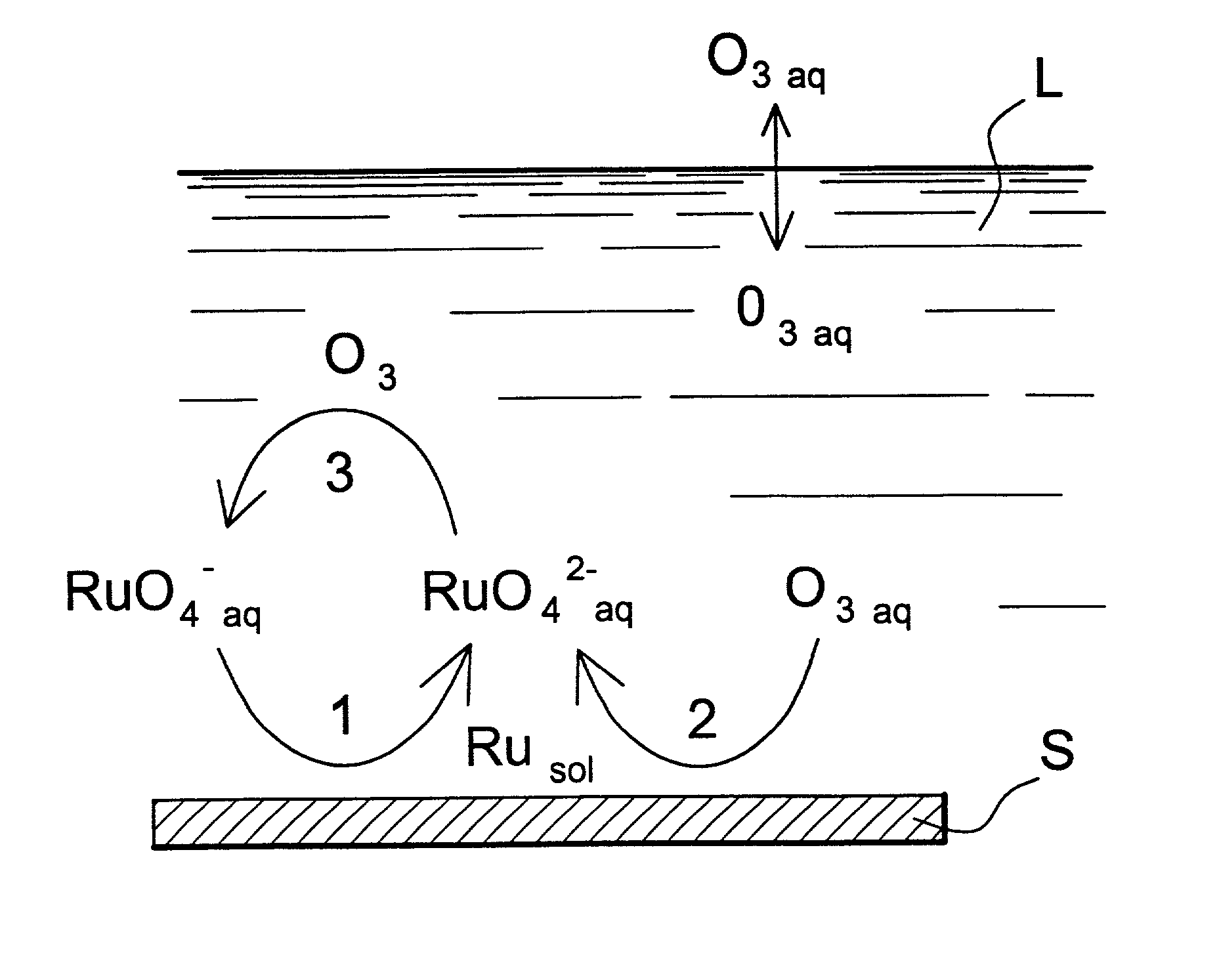
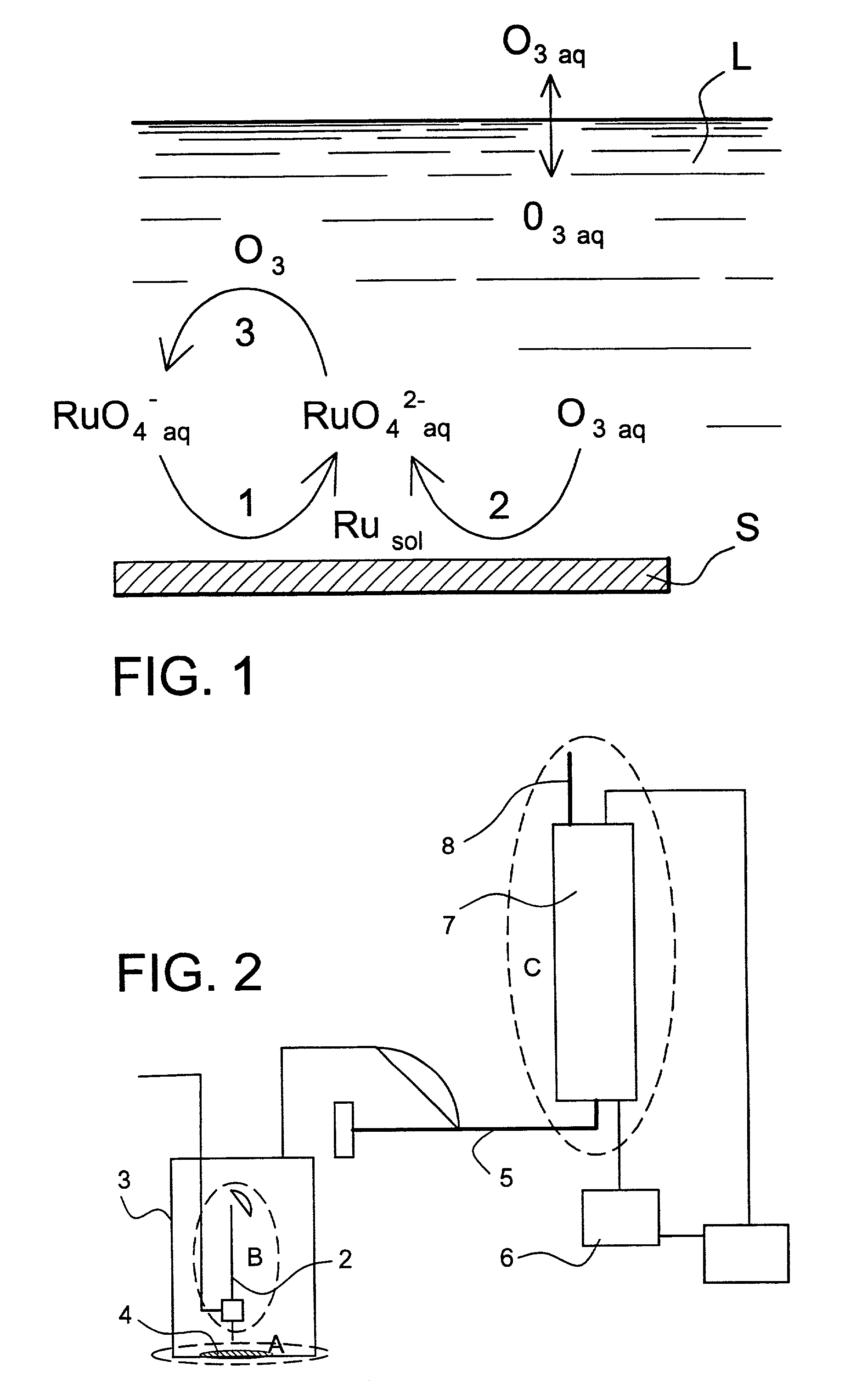
[0042] The process according to the present invention therefore allows continuous regeneration of the perruthenates from the ruthenates formed by the dissolution of the ruthenium deposits, and, if appropriate, putting part of the ozone, which can act directly on the ruthenium deposits, into solution.
[0044] The injection of the gaseous regeneration agent, according to the process of the present invention, advantageously allows continuous renewal of the solid / liquid interface between the basic solution used for dissolving the ruthenium deposits and the surface that needs to be treated, thus favouring the dissolution reactions of the insoluble species, in other words, the deposits.
[0053] According to the invention, the contact stage may be carried out at a temperature from 5 to 50.degree. C., for example at ambient temperature, and for example at a temperature from 15 to 30.degree. C. Higher temperatures reduce the solubility of ozone and increase the rate of consumption of molecular ozone through reaction with the OH--.
[0060] Apart from the advantages mentioned above, the cost of treating the dissolution effluent from the process according to the present invention is low, due to the fact of that the oxidising agent can be regenerated.
[0061] Moreover, the risks of corrosion of austenitic steels in certain installations by ozone in basic media are much reduced. In fact, the range of passivation of austenitic steels in basic media is very wide, from between 0.200 and 1,400 V / ENH, which limits the risks of corrosion when it is necessary to have a potential of around 0.6 V / ENH in order to obtain the ruthenates and perruthenates in basic media.

Problems solved by technology

it uses sulphates, which is a disadvantage in operational terms and can cause problems of corrosion in acid media in certain grades of steel such as austenitic steel.
Other oxidisers in alkaline media have been considered, such as Mn.sup.VII in the form of KMnO.sub.4, but the precipitation phenomena of reduced Mn.sup.II leads to part of the Ru being entrapped in the radioactive sludge, which is difficult to treat.
Oxidation processes in acidic media have the disadvantage of leading to high volatilisation of the ruthenium in the form of ruthenium tetra-oxide RuO.sub.4, which leads to aerial contamination of installations by reductive polymerisation in the form of (RuO.sub.2)x.
Moreover, oxidising processes in acidic media have the disadvantage of being more sensitive in terms of the corrosion resistance of installations made out of austenitic steel with a quite narrow passivation range.
This process cannot be used for cleaning up reprocessing plants for several reasons:
However, it is not possible to heat, without high cost, all of the circuits that need to be decontaminated.
this process means that a trapping reactor has to be created, which constitutes an awkward modification to the installation.
This is not an objective in the case of cleaning up reprocessing plants.

Method used


Image

  • Dissolution and decontamination process
  • Dissolution and decontamination process
  • Dissolution and decontamination process

Examples


example 1

[0066] Rate of dissolution of a deposit of ruthenium as a function of the perruthenate concentration in an aqueous solution of perruthenate according to the process of the present invention.

[0067] Table 1 below illustrates how the rate of dissolution of a deposit of ruthenium is influenced by the concentration of ruthenates, by showing the time required for dissolution of a deposit of 0.2 g of hydrated ruthenium dioxide by a gaseous ozone flow of 4.2 g.h.sup.-1 in 0.5 molar sodium hydroxide. The volume of the reactor was 3 liters. Each of the reactions was carried out under similar hydrodynamic conditions at 20.degree. C.

[0068] The chemical reactions that take place are shown schematically in FIG. 1. In this figure, S=surface covered by the ruthenium deposit and L=basic aqueous solution.

1TABLE 1 Change in the rate of dissolution as a function of the initial concentration of ruthenate Ruthenate concentration (in mol.1.sup.-1) Reaction time (minutes) 0 12 10.sup.-4 6 10.sup.-3 2

[0069]...

example 2

[0070] Process according to the present invention with and without a gaseous regeneration agent.

[0071] Table 2 shows the oxidising potential of an aqueous sodium hydroxide solution, with or without oxygen or ozonised oxygen gas mixing.

2TABLE 2 Oxidising potential of sodium hydroxide solutions in the presence of ozone Medium Potential (mV / ENH) Sodium hydroxide 1 mol.1.sup.-1 60 Sodium hydroxide 1 mol.1.sup.-1 + 110 O.sub.2 Sodium hydroxide 1 mol.1.sup.-1 + 220 O.sub.2 / O.sub.3

[0072] Table 2 shows that introducing ozone into the solution considerably increases the oxidising power of the solution and allows the oxidising reactions of the different rutheniated species that have to be solubilised to take place.

[0073] Table 3 shows the change in the oxidising potential of a sodium hydroxide solution in the presence of ozone as a function of the ozone concentration.

3TABLE 3 Change in the potential as a function of the sodium hydroxide concentration Sodium hydroxide concentration (mol.1.sup....

example 3

[0077] Effect of temperature on the process according to the present invention.

[0078] Table 5 shows the reduction in the molecular ozone concentration in solution as a function of the temperature in a solution of NaOH=1 mol.l.sup.-1.

5TABLE 5 Change in the oxidation potential as a function of the temperature. Temperature (.degree. C.) Potential (mV) 25 300 40 200

[0079] Table 6 illustrates how the reaction rate is independent of the temperature between 20 and 40.degree. C., by showing the time required for the dissolution of a deposit of 0.2 g of hydrated ruthenium dioxide with a flow rate of gaseous ozone of 4.2 g.h.sup.-1 in 0.5 molar sodium hydroxide and under similar hydrodynamic conditions.

6TABLE 6 Change in the rate of decontamination as a function of the temperature. Temperature (.degree. C.) Reaction time (minutes) 20 11 40 12


PUM

PropertyMeasurementUnit
temperatureaaaaaaaaaa
concentrationaaaaaaaaaa

Abstract

The present invention concerns a process for dissolving ruthenium deposits that are present on a surface and a process for decontaminating the internal circuits of nuclear fuel reprocessing plants using the said dissolution process. The process according to the invention comprises bringing the said surface into contact with an aqueous solution of perruthenate, with the said aqueous solution having a pH equal to or greater than 12, so that the ruthenium is oxidised.

Description

[0001] The present invention concerns a process for dissolving ruthenium deposits that are present on a surface and a process for decontaminating the internal circuits of nuclear fuel reprocessing plants using the said dissolution process.[0002] The present invention therefore concerns, in particular, the decontamination of internal circuits in irradiated nuclear fuel reprocessing plants. The process according to the present invention makes it possible to remove deposits composed, in part, of ruthenium from the pipes and other equipment in such plants.[0003] Radioactive ruthenium, in other words the isotopes .sup.106Ru and .sup.103Ru, or stable ruthenium, make up part of the fission products in nuclear fuels after irradiation in a reactor. In a general manner, in fuel irradiated at 34,000 megawatts / day, the level of ruthenium is around 0.2% of the initial weight of uranium.[0004] During the various reprocessing stages for irradiated fuels, most of this ruthenium is found in the circ...

Claims


Application Information

Patent Timeline
Patent Type & Authority Applications(United States)
IPC IPC(8): G21F9/28C01G55/00C23F1/40G21F9/00
CPCC01G55/00G21F9/001C23F1/40
Inventor FULCONIS, JEAN-MICHELDELAGRANGE, JACQUESDALARD, FRANCIS
Owner COMMISSARIAT A LENERGIE ATOMIQUE ET AUX ENERGIES ALTERNATIVES
Learn More