
Vortex flowmeter

a flowmeter and vortex technology, applied in the direction of instruments, liquid/fluent solid measurement, volume/mass flow by dynamic fluid flow effect, etc., can solve the problems of unreliability of conventional measurement, increased uncertainties in flow rate measurement, and/or slower determination of flow rate, so as to improve the accuracy of flow rate measurement and achieve greater accuracy and speed.

Inactive Publication Date: 2002-09-19
SCHNEIDER ELECTRIC SYST USA INC
View PDF39 Cites 92 Cited by
  • Summary
  • Abstract
  • Description
  • Claims
  • Application Information

AI Technical Summary

Benefits of technology

[0007] Techniques are provided for improving the accuracy of flow rate measurement over a greater range of flow rates. In particular, the techniques permit flow meters to measure low flow rates as well as medium and high flow rates with greater accuracy and speed.
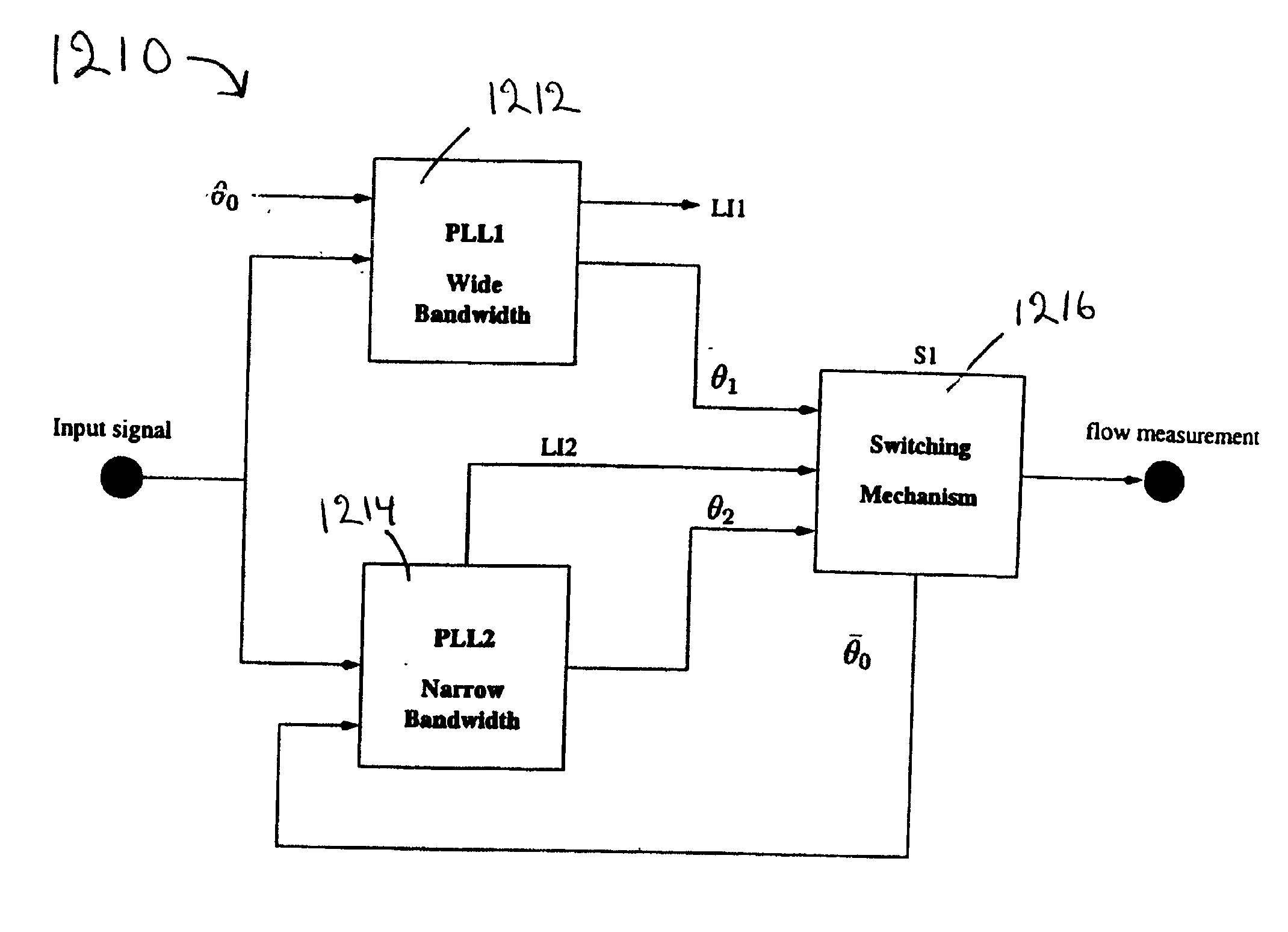
[0015] One of the PLLs (a "first" PLL) may be operable to lock onto the flow sensor signal faster than any other PLL, and another one of the PLLs (a "second" PLL) may be operable to lock onto the flow sensor signal with greater accuracy and greater immunity to noise than the first PLL. The switch may be operable to switch the output signal generated by the signal processor from an output signal of the first PLL to an output signal of the second PLL when the second PLL locks onto the flow sensor signal. When so implemented, the first PLL will attain lock quickly and ensure some stability during start-up and large transients, whereas the more accurate second PLL will ensure higher accuracy and better tracking of the vortex signal (and hence a better evaluation of the flowrate of the material through the passage).
[0017] One particular method of determining a flow rate sensed by a vortex flowmeter may include inputting to a signal processor an input signal having sinusoidal characteristics. The signal processor may include a first PLL having a first bandwidth and a second PLL having a second bandwidth narrower than the first bandwidth. The method may include locking into the frequency of the input signal using the first PLL, which has a fast loop filter having a large natural frequency to enable the first PLL to lock quickly into the frequency of the input signal. Next, the method may include locking into the frequency of the input signal accurately using the second PLL, which has a slow loop filter having a small natural frequency to enable the second PLL to lock into the frequency of the input signal more accurately and with greater immunity to noise than the first PLL. A lock indicator signal may be generated when the second PLL is locked into the frequency of the input signal.
[0022] The multiple PLLs can be interpreted as providing a narrow band-pass filter around the vortex shedding frequency. The noise-rejection performance of the multiple PLLs is designed to give the same or better noise-rejection performance than conventional vortex signal processors at the minimum flow rate of the vortex flowmeter. The bandwidth of conventional vortex signal processors varies with the flow rate, giving best noise-rejection performance at minimum flow rate. As the flow rate increases, however, the bandwidth of conventional vortex signal processors increases and the noise-rejection performance is degraded. Note that the vortex signal has high SNR at high flow rates, so that having a narrow band-pass filter in high flow rates is not as important as in low flow rates, where the SNR is low. The multiple (e.g., dual) PLL approach, however, provides the same noise-rejection performance of conventional vortex signal processors in the minimum flow-rate (or even better) over the full range of operation of the flowmeter (i.e., the bandwidth of the dual PLL filtering is independent of the flow rate). Therefore, some of the benefits of using dual PLLs instead of the conventional vortex signal processors include: better precision in high and low flow rates, significant improvement in the tracking performance, and extending the turn-down ratio of the vortex flowmeter.

Problems solved by technology

Below this threshold, accuracy of conventional measurement becomes unreliable.
Therefore, at low flow rates, the decreased amplitude of the vortex shedding pressure and the increased effect of noise on the measurement system lead to greater uncertainties in the flow rate measurement and / or slower determinations of flow rate.

Method used


Image

  • Vortex flowmeter
  • Vortex flowmeter
  • Vortex flowmeter

Examples


Embodiment Construction

[0055] Improvements to vortex flowmeter signal processing in both digital and analog implementations are provided.

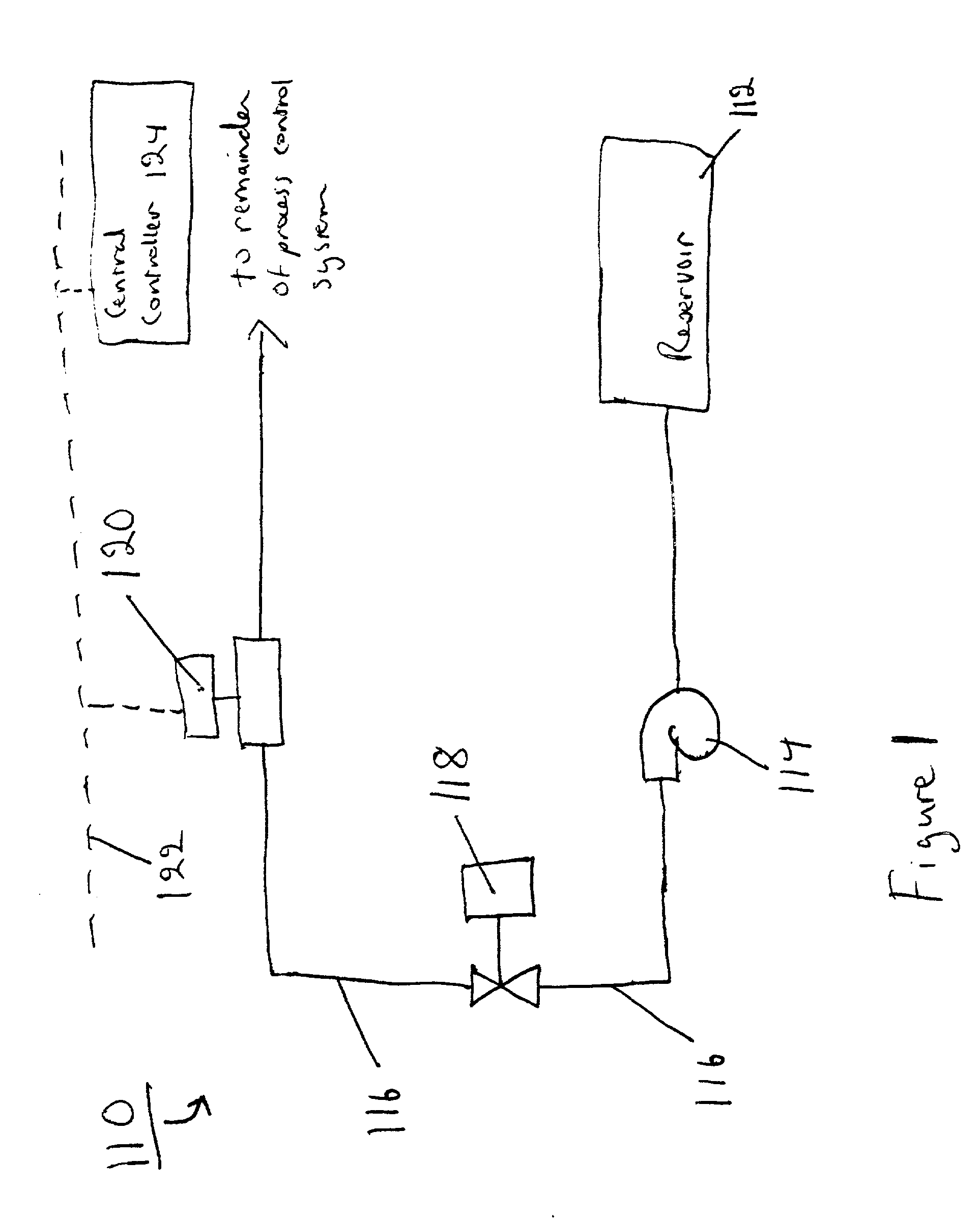
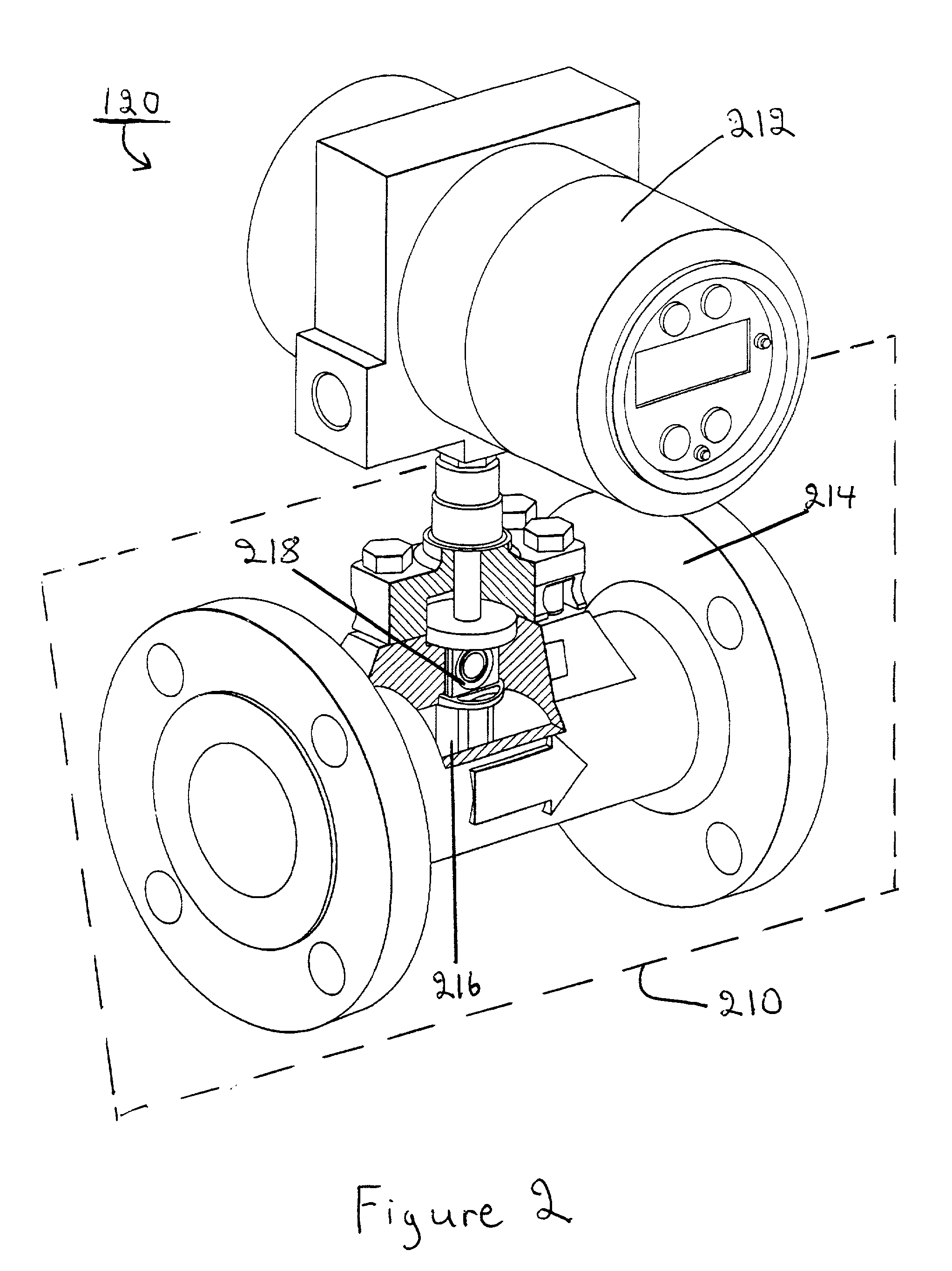
[0056] FIG. 1 illustrates a simplified process control system 110, or flow rig, which is one implementation in which the vortex flowmeter can be used. The flow rig 110 may include a reservoir 112, a pump (e.g., a centrifugal pump) 114, conduit portions 116 (e.g., pipes having a 2 inch diameter), a valve 118 to control the flow rate, and a vortex flowmeter 120. Various other process control devices or field devices may be included in the process control system 110, depending on the specific process control application. Furthermore, the process control system 110 may include a communication network 122 for monitoring and controlling the various devices of the process control system 110.

[0057] The communication network 122 can be implemented using a typical two-wire communication configuration. The communication network 122 can provide analog (e.g. 4-20 mA signals), digital...


PUM


Abstract

A process variable transmitter, implemented in a dual PLL structure, includes a first PLL having a first bandwidth producing a first output signal, and a second PLL having a second bandwidth narrower than the first bandwidth of the first PLL. The first and second PLLs are operable to lock into a frequency of an input signal and produce first and second output signals, respectively. The second PLL is operable to lock into the frequency of the input signal with greater accuracy and greater immunity to noise than the first PLL. A switch is operable to switch an output signal of the process variable transmitter between the first output signal and the second output signal.

Description

CROSS-REFERENCE TO RELATED APPLICATIONS[0001] This application claims priority from U.S. Provisional Application No. 60 / 261,196, filed Jan. 16, 2001, and titled VORTEX FILTER, which is incorporated by reference.TECHNICAL FIELD[0002] This invention generally relates to digital and analog flowmeters.BACKGROUND[0003] Flowmeters provide information about materials being transferred through a conduit. For example, a flowmeter may provide a direct indication of the velocity and volume of the material being transferred through the conduit. Mass flowmeters measure the mass of the material, and density flowmeters measure the density of the material.[0004] One type of flowmeter is a vortex-shedding meter, or vortex flowmeter. Vortex flowmeters operate using techniques based on a vortex shedding phenomenon known as the Karman effect. In the vortex flowmeter, a bluff body is placed in the conduit (e.g., a pipe) in the path of the material passing through the conduit. The bluff body sheds Karman...

Claims


Application Information

Patent Timeline
Patent Type & Authority Applications(United States)
IPC IPC(8): G01F1/32
CPCG01F1/329G01F1/3287
Inventor CLARKE, DAVID W.GHAOUD, TAREK
Owner SCHNEIDER ELECTRIC SYST USA INC
Learn More