
Tissue-lifting device

a tissue-lifting and facelifting technology, applied in the field of facelifting devices, can solve the problems of inability to follow or maintain the plane, difficulty in "feeling" the fibrous plane, and the risk of affecting the smooth undermining of adjacent tissues, so as to quickly and safely separate tissue planes

Inactive Publication Date: 2002-09-12
WEBER PAUL J
View PDF0 Cites 217 Cited by
  • Summary
  • Abstract
  • Description
  • Claims
  • Application Information

AI Technical Summary

Benefits of technology

[0011] It is an object of the present invention to provide a method and a device that can be used by surgeons to quickly and safely separate tissue planes.
[0012] It is another object of the invention to provide a facial tissue lifting and facial tissue-tightening device that easily maintains the proper dissection plane by constraining the position of the lysing segments within the desired tissue layers.
[0013] Another object of the invention is to provide an undermining device that can position lysing surfaces at a proper level for controlled and safe fibrous tissue separation during a brow-lift.
[0014] In one embodiment the device is comprised of a hollow or solid shaft with a relatively planar tip that can be easily positioned between dissection planes in tissue and then manipulated to separate tissue planes and lyse fibrous tissue. Thermal effects of externally applied energy transmitted to the collagenous (dermal, superficial platysma musculature and other) tissues of the face in the facelift plane can cause cosmetically desirable contraction of the dermal tissues with beneficial tightening of the facial tissues. Accordingly, the invention provides an internally transmissible energy source and delivering means, which delivers energy to the distal end of the shaft. Various forms of energy may be used to augment tissue change in the wake of instrument passage including lasers, thermal, and RF and ultrasound energy.
[0016] Although an embodiment provides a shaft that has a cross-sectional shape that is approximately rectangular, acceptable alternative versions of the shaft may be oval, semi-circular, or trapezoidal in cross-section. Although an embodiment provides a tip having a shape with alternating protrusions and recessions, acceptable alternative versions of the tip shape may be semicircular, lenticulate or geometric. The same protrusions that exclude critical anatomical structures (such as blood vessels or nerves) by virtue of their relationship to the cutting recessed segments also serve to position the depth of the present invention with respect to various tissues such as the lower dermal layer of the face. The spacing and the relationship of the protrusions (bulbs) and lysing segments aid in maintaining proper tracking of the instrument when the surgeon forces the instrument through the target tissue to be treated. The beneficial feeling of "tracking" is instantly palpable by the surgeon on forced device motion; thus the surgeon requires no monitor to know how the device is moving. Both the number and spacing of bulbous-structures will aid in reducing wobble or lateral (horizontal) slippage during forward thrusting of the shaft. Vertical slippage of the instrument within tissue is prohibited if a properly directed upward force is applied by the surgeon's hand with forward passage of the instrument. This is because the width of the protrusions / bulbs helps maintain the correct distance between the lysing segments and the delicate underside of the superficial skin or dermis.
[0017] Beneficially, the tip of the device and the action of the device can be felt / appreciated without direct visualization (endoscope). The surgeon can blindly and confidently know that the device is tracking in the proper tissue plane and location. The feel of the device in the proper tissue plane is easily learned since measurable resistance without visualization through the facial tissues can immediately tell the surgeon the location and the amount of undermining that has occurred at that location.

Problems solved by technology

Planes between the soft internal organs are usually loose and spongy.
Sharp instrument undermining is usually performed to separate highly fibrous or collagenous tissues; however, sharp undermining suffers from the risk of penetrating adjacent tissues inadvertently because of loss of ability to follow the desired plane.
Inability to follow or maintain the plane in sharp undermining is frequently due to limited visibility, difficulty "feeling" the fibrous plane, or scarring (collagen fibrosis) resulting from previous trauma or surgery.
Even experienced surgeons may from time to time lose the correct plane of sharp undermining; great skill is required.
Unfortunately, blunt undermining between highly fibrous tissues such as the human face usually causes tunneling with thick fibrous walls.
Disadvantages of the current face-lifting and brow-lifting techniques are numerous and have resulted in undesirable outcomes and litigation.
Inadvertent lateral cutting or tissue trauma may be difficult to control.
Thus, tissue positioning of a cutting edge is the paramount problem with current face-lifting / undermining technology.
In addition, speed of separation is important to reduce the time that the patient is exposed to anesthetic drugs; time duration of anesthesia may be directly related to the risk of anesthetic complications.
Use of prior art undermining devices (including scissors, sharp rhytisectors, etc.) in these planes during cosmetic surgery has, at times, resulted in unwanted cutting, trauma or perforation of adjacent structures.
Unfortunately, scissors with 3 dimensional or "bulbous", spheroidal tips cannot close completely to cut or define a plane in target tissues.
Scissors with 2 dimensionally rounded tips can close all the way to cut target tissue however the shape and tips are prone to inadvertently wander undesirably between tissue planes because of a lack of a third dimensional limitation.
However, Farin's device is not intended for separating tissue planes and is susceptible to catching, tearing or puncturing the tissue when manipulated.
Just as sharp undermining or dissection has its disadvantages, as previously mentioned, blunt dissection suffers from its own difficulties as well.
However, disadvantageously for the aforementioned intentions, traditional purely-blunt-object undermining often results in random motion or uncontrollable-slippage of the underminer tip on forward motion and thusly loss of precise tracking of the underminer through target tissue.
Additionally, thickened devices often "hang-up" or get caught in various tissue structures for example collagenous bands.
Currently it takes many surgeons varying amounts of time often exceeding 10-20 minutes and even an hour to dissect the scalp brow-lifting plane and coagulate blood vessels, especially if coagulation is needed for unsealed emissary vessel trauma.

Method used


Image

  • Tissue-lifting device
  • Tissue-lifting device
  • Tissue-lifting device

Examples


Embodiment Construction

[0026] The present invention provides a device to be used by surgeons that provides quick and accurate face lifting and brow lifting maneuvers and maximizes efficiency, reduces bleeding and is capable of tissue modification via various energy applications. The device is comprised of an undermining shaft with or without specialized tips or energy delivering windows that can easily travel along dissection planes within tissue and be manipulated to separate tissue planes and lyse fibrous tissue as well as alter tissue planes via energy application.

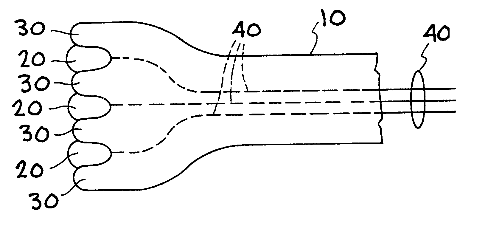
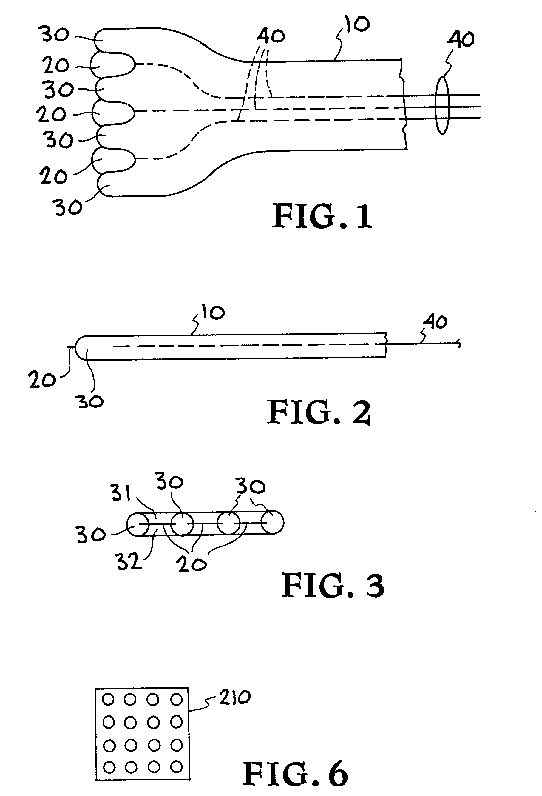
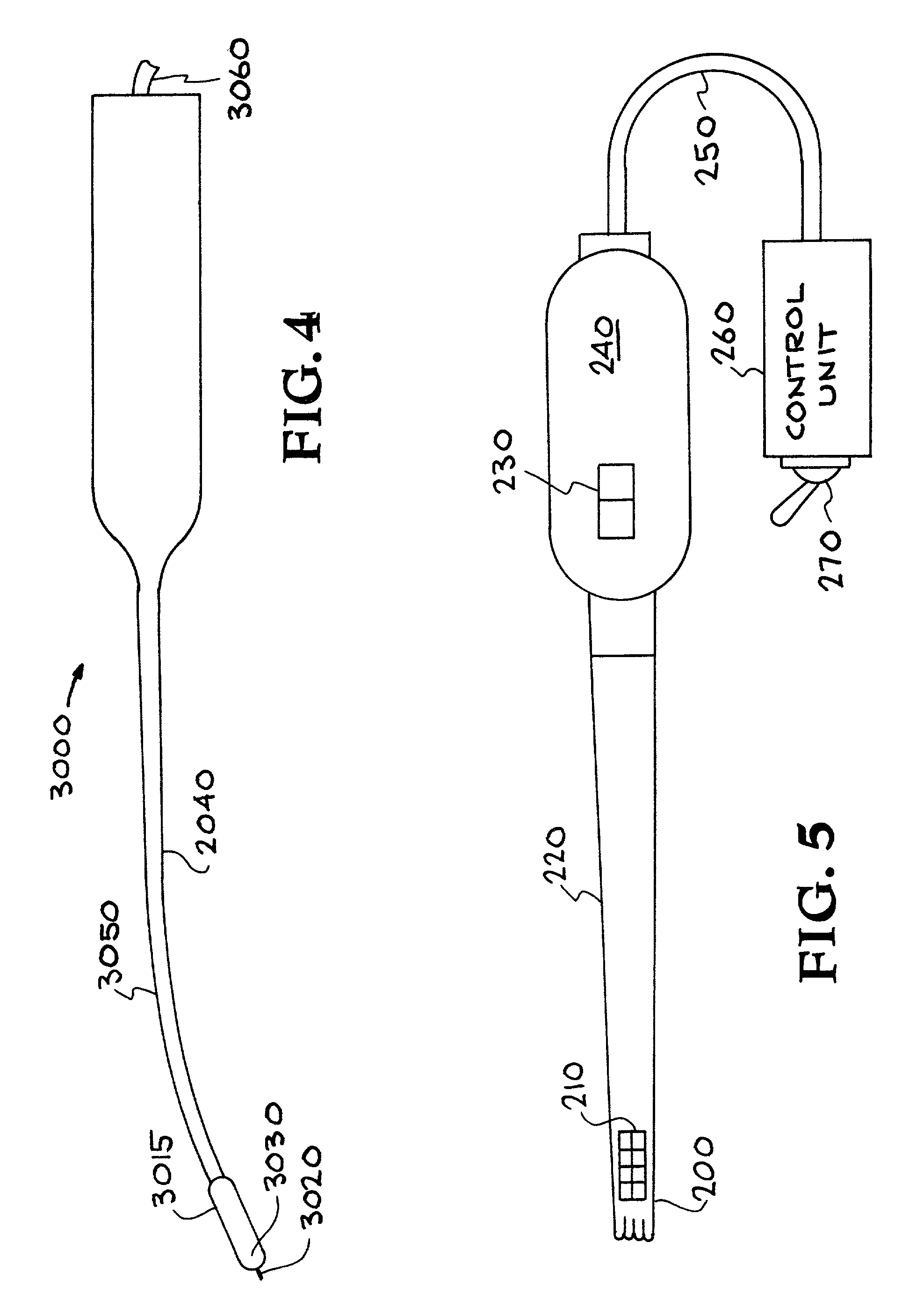
[0027] FIG. 1 shows a partial top view of the distal tip of an embodiment of a brow / face-lifting device 10 of the present invention. In some embodiments, the lysing segments (with a cutting edge) are configured to transmit electrical energy and / or RF energy, e.g., to aid in cutting or cauterizing the lysed tissue. In other embodiments, the lysing segments are not configured to transmit electrical and / or RF energy. In such cases, the lysing se...


PUM


Abstract

A device is described that can be used by surgeons to provide accurate tissue-lifting and tightening maneuvers that uses minimal external incisions, enhances accuracy, reduces inadvertent consequences while speeding the procedure. The device is comprised of a shaft with a relatively planar but possibly lenticulate or even slightly curved tip that can divide and energize various tissue planes causing net contraction via the fibrous tissue modification. Various forms of energy can also be delivered to cause desirable tissue alterations.

Description

[0001] This application is a continuation-in-part of U.S. patent application Ser. No. 09 / 475,635, titled "Surgical Device for Performing Face-Lifting Using Radiofrequency Energy", filed Dec. 30, 1999, incorporated herein by reference, U.S. patent application Ser. No. 09 / 478,172, titled "Surgical Device for Performing Face-Lifting Using Electromagnetic Radiation", filed Jan. 5, 2000, incorporated herein by reference, U.S. patent application Ser. No. 09 / 588,436, titled "Thermal Radiation Facelift Device", filed Jun. 6, 2000, incorporated herein by reference, and U.S. patent application Ser. No. 09 / 749,497, titled "Face-Lifting Device", filed Dec. 22, 2000, incorporated herein by reference.BACKGROUND OF THE INVENTION[0002] 1. Field of the Invention[0003] The invention relates to face-lifting devices, and more specifically, it relates to a surgical device that can quickly and safely separate tissue planes. In addition, the invention relates to a face-lifting device that can apply energy...

Claims


Application Information

Patent Timeline
Patent Type & Authority Applications(United States)
IPC IPC(8): A61B17/00A61B18/00A61B18/08A61B18/14A61B18/18A61B18/20A61B18/22A61N7/02
CPCA61B18/08A61B18/1402A61B18/201A61B18/203A61B2017/00084A61B2017/0046A61B2017/00761A61B2017/00792A61B2017/00853A61B2018/00017A61B2018/00452A61B2018/1807A61B2018/2272A61N7/022
Inventor WEBER, PAUL J.WEBER, MICHAEL ROBERTDA SILVA, LUIZ B.
Owner WEBER PAUL J
Learn More