Deeply-integrated adaptive GPS-based navigator with extended-range code tracking

Inactive Publication Date: 2002-09-12
CHARLES STARK DRAPER LABORATORY
View PDF0 Cites 32 Cited by
  • Summary
  • Abstract
  • Description
  • Claims
  • Application Information

AI Technical Summary

Benefits of technology

[0013] The philosophy of the approach taken in the present invention differs from that of previous techniques; as a result, the navigation system architecture and processes employed yield significant improvements in navigation system performance, both in code tracking and reacquisition, and in carrier tracking and reacquisition. The improvements are particularly significant at low signal / noise ratios, where conventional approaches are especially susceptible to loss of code lock or carrier lock.
[0014] The present invention approaches the problem as a navigation problem, where the overall goal is to calculate an optimal, or "best", estimate of the components of a specified navigation state vector, given an initial estimate of the state vector and the past history of measurements. The measurements to be used are referred to herein as "raw" measurements, consisting of a least in-phase (I) and quadrature (Q) data obtained from one or more correlators operating on received GPS signals. Additional navigation sensors may be used, depending on the application at hand, to enhance navigation system performance. These sensors include, but are not limited to, inertial sensors (gyros and accelerometers), altimeters, radars and electro-optical devices. By using the "raw" measurements from all of the sensors, potential loss of information due to preprocessing operations is prevented.
[0017] The technique of the present invention is not dependent in any manner on a priori notions of tracking filters, phase lock loops, delay lock loops, and the like, which are commonly used. Instead, the navigation system architecture and processes flow naturally from the problem description and the characterization of the measurements from GPS and other sensors. This leads to an architecture which is amenable to single processor integration, eliminating the modular (and sub-optimal) architectures of current designs.
[0019] A bank of correlators and a processing architecture based on nonlinear estimation techniques are employed to maintain code track: through extremely high jamming environments. The number of correlators are optionally extendable, to allow for optimal code loop reacquisition following GPS signal dropout, eliminating the need for time-consuming reacquisition as employed by conventional direct-search techniques. The outputs of each correlator in the correlator bank are preferably weighted to provide a fully optimized navigation solution.
[0038] In a preferred embodiment of the seventh aspect, the state gain functions and error covariances of the navigation state are further based on estimates of the radio navigation data signal power and noise power. The conditional moments preferably comprise non-linear functions of a line-of-sight error variance, in turn a function of the error covariance of the navigation state, and the integrity management unit preferably monitors and limits the signal and noise power values. The integrity management unit preferably further limits growth rate of the error covariances. Inertial data is preferably sensed by inertial data sensors and the growth rate of the error covariances are limited to an upper bound based on estimated accuracy of the inertial sensors. The integrity management unit may further monitor and maintain the positive-definiteness of the error covariance matrix, and may further limit estimated change of the navigation state.

Problems solved by technology

In modern GPS-based navigation systems, interference can have adverse effects on GPS receiver code and carrier tracking, resulting in degraded navigation system performance.
Thus, recovery of the GPS signal, even with no interference, cannot be accomplished without special design techniques such as spread spectrum.
As a result, current systems are far from optimal in terms of interference rejection and navigation accuracy.

Method used


Image

  • Deeply-integrated adaptive GPS-based navigator with extended-range code tracking
  • Deeply-integrated adaptive GPS-based navigator with extended-range code tracking
  • Deeply-integrated adaptive GPS-based navigator with extended-range code tracking

Examples


Embodiment Construction
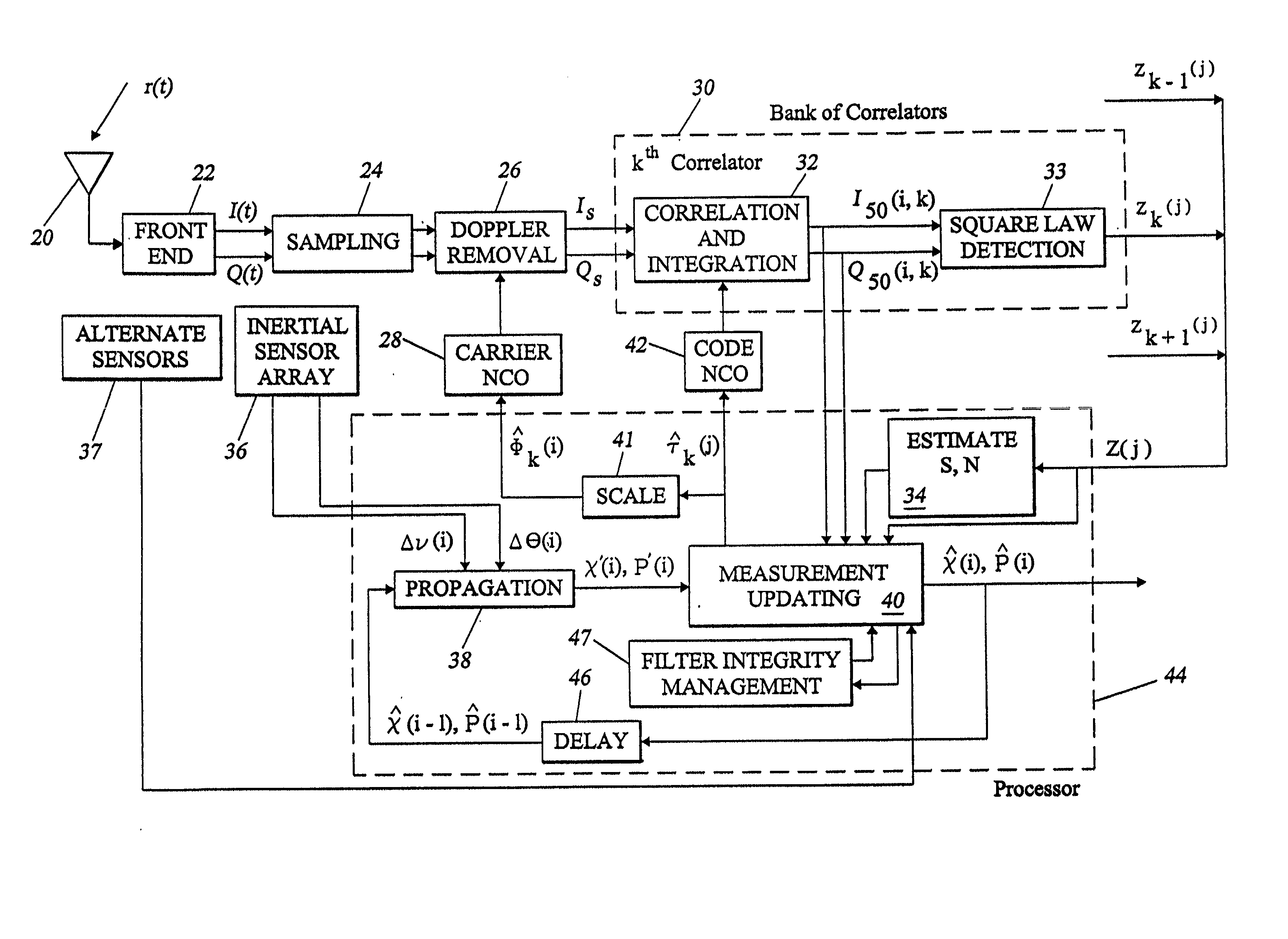
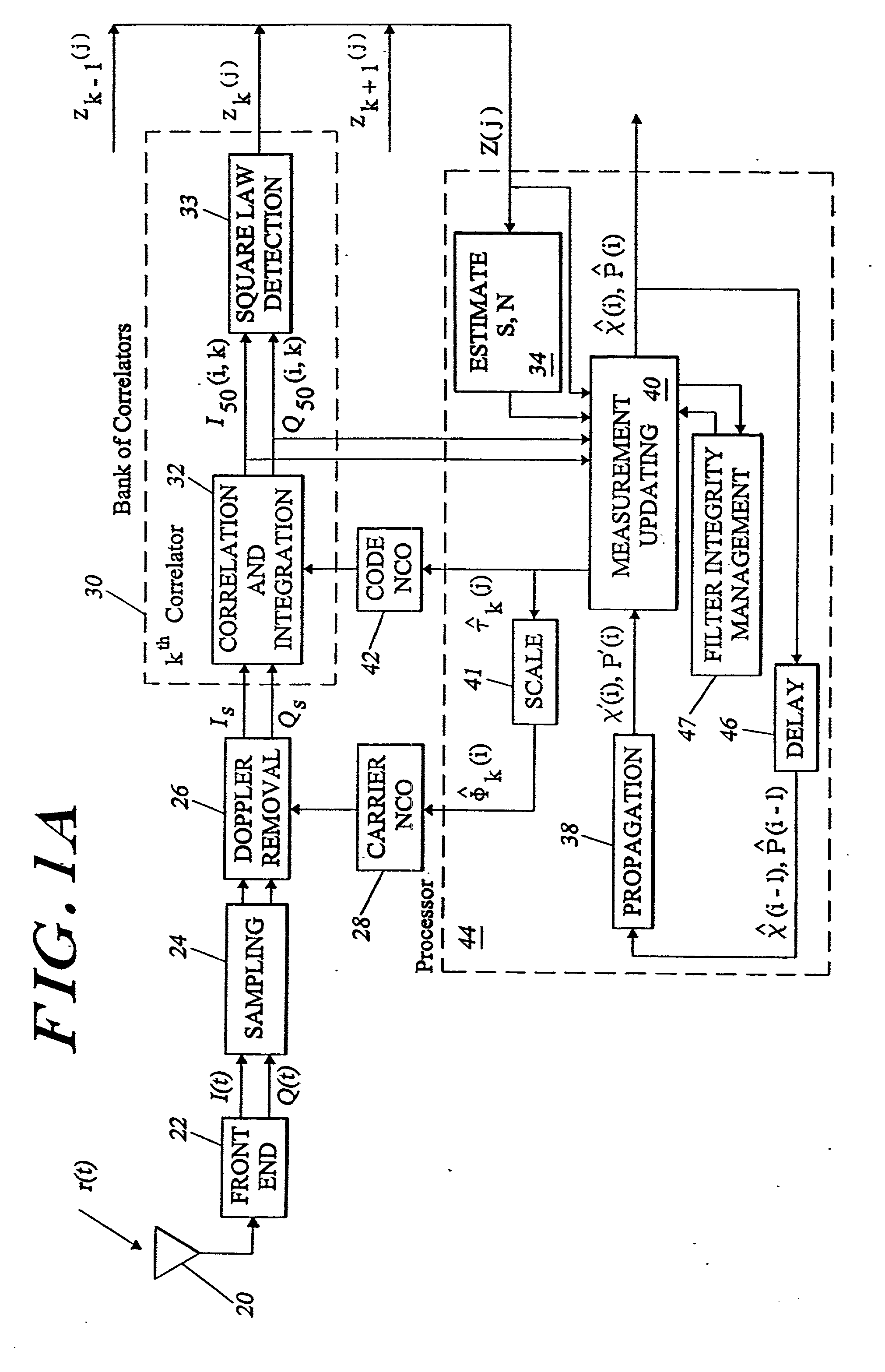
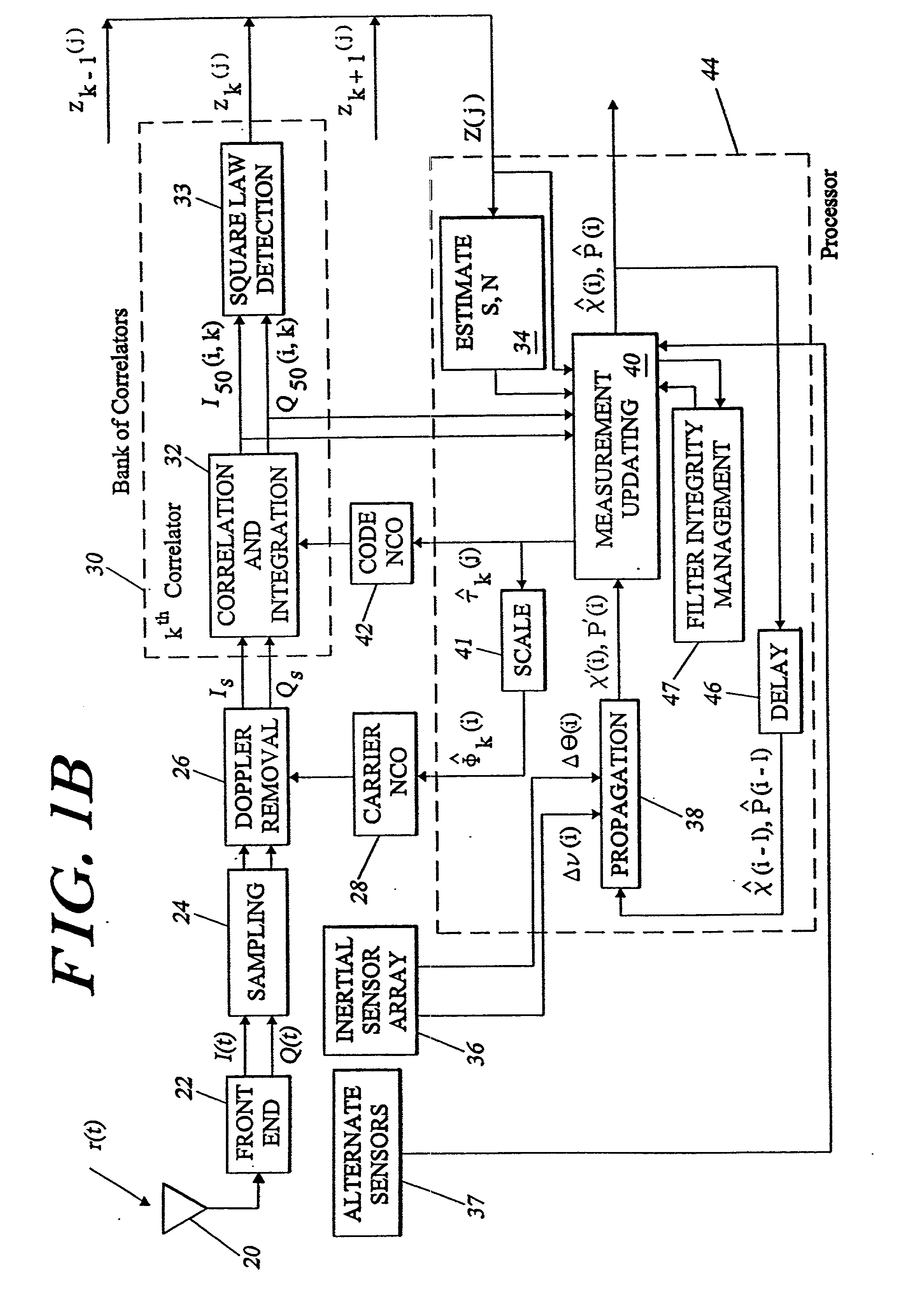
[0050] Overview

[0051] GPS code tracking employs knowledge of transit time and the speed of light to determine relative position along the satellite-to-receiver line-of-sight to enable specified worldwide navigation accuracies of approximately 100 meters (95% probability) for civilian C / A code and approximately 20 meters for dual-frequency PCY) code. These accuracies are often exceeded in practice. Navigation errors may be reduced to approximately 1 meter if nearby GPS transmitters, such as pseudolites, are employed to eliminate propagation errors.

[0052] Carrier tracking is maintained in modern systems using Doppler (velocity) measurements which reflect a change in the received signal carrier frequency. If the interference environment is benign, then carrier tracking may be used to achieve accuracies even greater than those achievable by code tracking, on the order of 1 centimeter. However, the carrier tracking threshold is approximately 15 dB below the code tracking threshold, makin...


PUM


Abstract

A system and method for generating a multidimensional navigation solution utilizes Global Positioning System (GPS) data to obtain highly reliable and accurate navigational solutions in high interference and dynamic environments, at a performance level which has been heretofore unattainable. Additional sensors such as inertial (gyros and accelerometers), altimeters, radars, etc. may be employed in a deeply integrated configuration. The approach taken in the present invention differs from that of previous techniques through its exploitation of nonlinear filtering methods; as a result, the navigation system architecture and processes employed yield significant improvements in navigation system performance, both in code tracking and reacquisition, and in carrier tracking and reacquisition. The improvements are particularly significant at low signal / noise ratios, where conventional approaches are especially susceptible to loss of code lock or carrier lock.

Description

BACKGROUND OF THE INVENTION[0001] Contemporary navigation systems commonly employ satellite navigation data derived from radio navigation receivers to determine the: location of a navigation platform. The satellite data is often augmented by data from additional sensors in order to improve navigation system performance in situations where satellite data may be available only intermittently or may be degraded by intentional or unintentional interference. For example, data from inertial sensors (accelerometers and gyros) may be used to allow full navigation solutions (position, velocity and attitude) to be maintained in the presence of satellite data dropouts over extended periods of time. Radio navigation data is generated by receivers specifically designed to receive and process radio signals transmitted from a plurality of space-based or ground-based terminals. The navigation sensors are generally, but need not be, collocated on the same navigation platform. Depending on the applic...

Claims


Application Information

Patent Timeline
IPC IPC(8): G01C21/16G01S1/00G01S5/14G01S11/02G01S19/21G01S19/26
CPCG01C21/165G01S19/21G01S19/26G01S19/47G01C21/1652
Inventor GUSTAFSON, DONALD E.DOWDLE, JOHN R.ELWELL, JOHN M. JR.
Owner CHARLES STARK DRAPER LABORATORY
Why Eureka
Try Eureka