Steering and braking in-line skate or roller ski

a technology of inline skates and roller skis, applied in the direction of skateboards, skis, sport apparatus, etc., can solve the problems of not steering, limiting the overall performance of skates in terms of speed, handling, range of terrain,

Inactive Publication Date: 2002-09-12
PAGE JAMES S +2
View PDF0 Cites 6 Cited by
  • Summary
  • Abstract
  • Description
  • Claims
  • Application Information

AI Technical Summary

Benefits of technology

0035] In still other embodiments, the braking assembly may utilize a drum brake instead of a disk. In that case, the drum or frictional contact surface may attach to the wheel hub, or may be integrally formed in the wheel hub, for example by steel inserts in a generally cylindrical surface of a cast or molded wheel hub assembly. A brake shoe assemb...

Problems solved by technology

This allows them to have a certain degree of stability as well as steerability, but makes them heavier than ideal, and limits their overall performance in terms of speed, handling, and the range of terrain on which they may be used.
However, they do not actually steer by weight displacement (although they may at first appear to do so).
For configurations with only two wheels and/ or longer wheelbases, steering by scrubbing the wheels is much more difficult.
Typically with these devices steering is accomplished by step turning, which is clumsy and difficult.
However, the known methods have drawbacks which have prevented them from being adopted for in-line skates or land skis, as discussed below.
This is complex from a manufacturing standpoint, and potentially unwieldy when used on a foot mounted device such as an in-line skate, roller ski, or the like.
This mechanism is unwieldy because the user's weight is applied to the frame from behind the front wheel, which requires substantially large and potentially heavy supporting members connecting the weight bearing portion of the frame to the pivot, and additional members to transfer forces between the pivot and the axle of the front wheel.
For a device with large wheels, this type of mechanism would require a potentially unwieldy frame structure, similar to those described above.
As in the case of U.S. Pat. No. 4,138,127, this mechanism requir...

Method used


Image

  • Steering and braking in-line skate or roller ski
  • Steering and braking in-line skate or roller ski
  • Steering and braking in-line skate or roller ski

Examples


Embodiment Construction

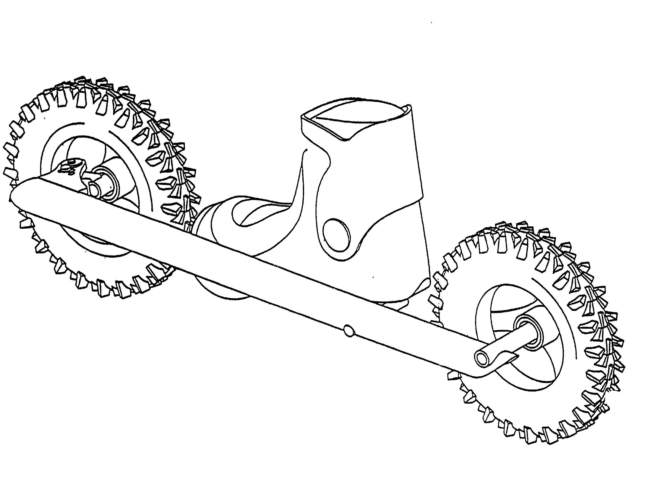
[0051] The invention will be discussed following a brief review of relevant features of certain prior art wheeled sports devices. In illustrating embodiments of the invention, certain preferred as well as several necessary mechanical components will be shown, for which common mechanical or automotive terminology is employed, with corresponding elements in different embodiments bearing the same numeral, but possibly an alphabetic suffix a.b . . . to distinguish among them. Among the elements appearing in the figures are a tire 10, wheel 11, damper sealing boot 12, wheel bearing assembly 13, wheel support assembly 14, kingpin 15, steering pivot assembly 16, damper housing 17, centering force mechanism 18, damper piston 19, steering link 20, chassis 21, steering axis 22, tire patch 23, fluid chamber 24, connecting pin 25, steering stop pin 26, steering lockout hole 27, steering limit track 28, suspension pivot 29, suspension link 30, and wheel rotation axis 31.

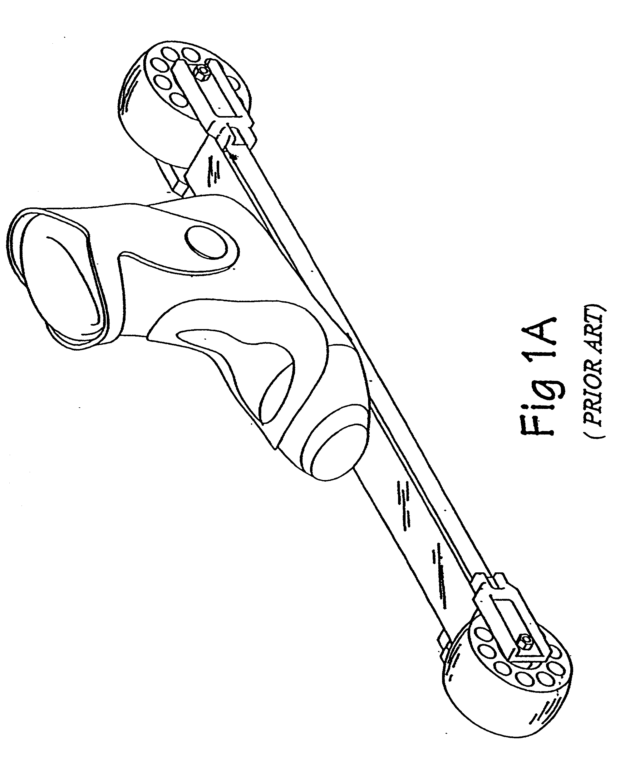
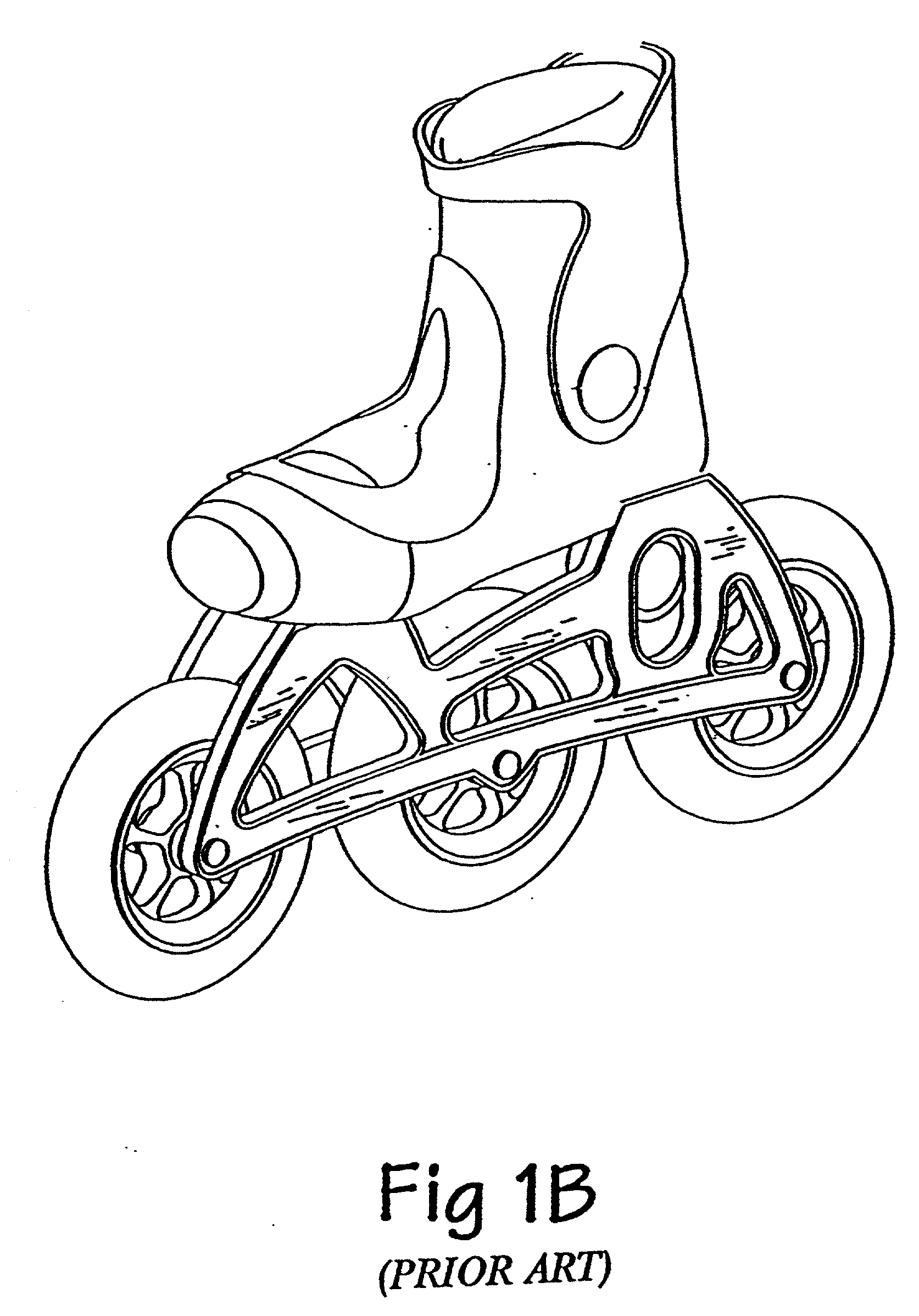
[0052] A survey of the pr...


PUM


Abstract

A steerable wheeled device such as an in-line skate or roller ski has a hollow or dish-shaped wheel, a wheel bearing, and a wheel support connecting the wheel to a steering structure that extending substantially within the outer radius of the wheel, and steers as the user's weight is displaced. The device preferably has a side-mounted chassis, and oversize wheel positioned in front and in back of the user's foot. The chassis may contain a damping and centering force mechanism to moderate behavior of the steering or suspension. Brakes such as drum or disk brakes are connected to one or more wheels and preferably actuated, e.g., with a boot-actuated linkage, such that braking occurs upon the user adopting a specific posture. In a preferred construction, the stance shifts weight back and/or down so that deceleration does not occur until the user has assumed a stable stance.

Description

REFERENCE TO RELATED APPLICATIONS[0001] This application is a continuation-in-part of International Patent Application PCT US99 / 26136 filed Nov. 5, 1999, of U.S. patent application Ser. No. 09 / 187,627 filed Nov. 6, 1998, and of U.S. Provisional Patent Application Serial No. 60 / 253,438 filed Nov. 28, 2000. The benefit of priority of each of the foregoing applications is hereby claimed pursuant to 35 U.S.C. .sctn..sctn. 119, 120, and they are all hereby incorporated herein by reference in their entirety.FIELD OF THE INVENTION[0002] The invention pertains to wheeled recreational devices such as skates, land skis and skate boards.[0003] Many wheeled devices have been invented with varying degrees of public acceptance and popularity. Some of the most widely known are for sport and recreation, such as roller skates. Although very functional and popular, roller skates steer using a bulky mechanism which requires wheels to be in pairs. This allows them to have a certain degree of stability ...

Claims


Application Information

Patent Timeline
IPC IPC(8): A63C5/035A63C17/06A63C17/14A63C17/16A63C17/22
CPCA63C17/045A63C17/064A63C17/1427A63C17/16A63C17/22A63C2017/1481
Inventor PAGE, JAMES S.BATHO, MARKPAGE, MATTHEW
Owner PAGE JAMES S
Why Eureka
Try Eureka