Method for braking a motor vehicle and motor vehicle

一种机动车、制动力的技术,应用在制动机动车领域,达到确保安全性的效果

Active Publication Date: 2016-12-28
AUDI AG
View PDF8 Cites 0 Cited by
  • Summary
  • Abstract
  • Description
  • Claims
  • Application Information

AI Technical Summary

Problems solved by technology

The disadvantage of this solution, however, is the additional installation space required and additional costs due to the installation of additional resistors

Method used


Image

  • Method for braking a motor vehicle and motor vehicle
  • Method for braking a motor vehicle and motor vehicle
  • Method for braking a motor vehicle and motor vehicle

Examples


Embodiment Construction

[0031] The examples set forth in detail below represent preferred embodiments of the invention.

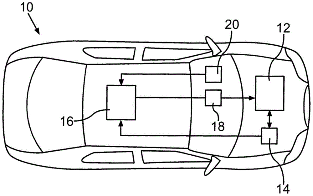
[0032] figure 1 A schematic illustration of motor vehicle 10 is shown in plan view. Motor vehicle 10 is preferably an electric vehicle or a hybrid vehicle. Motor vehicle 10 includes at least one electric machine 12 via which a drive torque for driving motor vehicle 10 can be generated. Motor vehicle 10 can also include a plurality of electric motors 12 , for example one electric motor 12 for each drive wheel. Furthermore, motor vehicle 10 includes an electrical energy store 14 which is electrically connected to electric machine 12 .

[0033] Electric machine 12 can be used not only to drive motor vehicle 10 but also to brake motor vehicle 10 . For braking, the electric machine 12 can be operated as a generator in a first operating mode, wherein it generates a corresponding generator braking torque. In a first operating mode, which is also referred to as regenerative braking o...


PUM


Abstract

The invention relates to a method for braking a motor vehicle (10) driven by the drive torque of at least one electric machine (12) electrically connected to an electric energy store (14), wherein in a first operating mode, at least one electric machine (12) is operated as a generator to generate a generator braking torque, and in a second operating mode the at least one electric machine (12) is thus supplied with electrical energy from the electric energy storage device (14) , so that a braking torque opposite to the driving torque is generated by the at least one electric motor (12).

Description

technical field [0001] The invention relates to a method for braking a motor vehicle which is driven by a drive torque of at least one electric machine. The invention also relates to a motor vehicle. Background technique [0002] For electric or hybrid vehicles which are driven by at least one electric motor, new requirements arise with regard to the braking system of the motor vehicle. In these motor vehicles, the electric machine for braking the motor vehicle can be operated as a generator. With this so-called recycling, it is possible to convert part of the kinetic energy of the motor vehicle back into electrical energy during braking. [0003] Since the braking torque of the electric machine is usually not sufficient to completely brake the motor vehicle, a friction brake is additionally installed which is able to provide the required braking torque. In the context of energy efficiency, however, it makes sense to convert as much of the kinetic energy of the motor vehi...

Claims


Application Information

Patent Timeline
Patent Type & Authority Patents(China)
IPC IPC(8): B60L7/00B60L7/10B60L7/12B60L7/14B60L7/26B60L11/00B60L11/18B60L15/20B60L3/00B60W20/14
CPCB60W20/14B60L50/52B60L50/40B60L50/51B60L3/0061B60L7/12B60L7/14B60L7/26B60L15/2009B60L2240/423B60L2240/36B60L2220/14B60W2540/12B60W2510/244B60W2710/105B60Y2300/89B60T2270/604B60T2220/04B60W30/18109B60W30/18127B60W10/184B60W20/00B60W10/08Y02T10/64Y02T10/70B60L7/006Y02T10/72B60L7/18B60L7/10
Inventor B·克莱克曼T-W·迈尔
Owner AUDI AG
Why Eureka
Try Eureka