
Medication delivery device with bended piston rod

a technology of piston rod and medication delivery device, which is applied in the direction of automatic syringes, instruments, infusion syringes, etc., to achieve the effect of greater mechanical stability, greater axial stiffness of rods, and greater rigidity

Inactive Publication Date: 2002-07-11
NOVO NORDISK AS
View PDF0 Cites 223 Cited by
  • Summary
  • Abstract
  • Description
  • Claims
  • Application Information

AI Technical Summary

Benefits of technology

[0014] An advantage of having a linear path of the piston rod between the driving wheel and the piston is that the risk of introducing errors in the displacement of the piston by the rod is reduced because a more direct drive of the piston is provided (i.e. the sources of mechanical inaccuracies from a remotely located driving wheel due to the curved path, extra friction of the guiding means, etc. are eliminated). Related advantages of this are that an improved dose accuracy may be achieved and that the requirements with respect to the power of the activating means are reduced, leading to a possible reduction in weight and volume of the device.
[0042] When the piston rod is at least partially made of a plastics material, it is ensured that a solution combining the benefits of using a plastics material (e.g. corrosion resistance) with those of other materials (e.g. greater mechanical stability, stiffness, etc.) may be provided.

Problems solved by technology

The problems of the prior art are that the driving means are located relatively far from the piston and require a relatively thick piston rod having a relatively high friction with the housing and the cartridge, thus requiring a relatively high power consuming motor to advance it and possibly introducing inaccuracies in the displacement of the piston, or that the means for advancing the tape-shaped piston rod, the take-up spool storing the unused part of the tape, and the drum or wheel that supports the U-shaped path of the tape are individual self-contained functional units, yielding a relatively complex solution.

Method used


Image

  • Medication delivery device with bended piston rod
  • Medication delivery device with bended piston rod
  • Medication delivery device with bended piston rod

Examples


Embodiment Construction

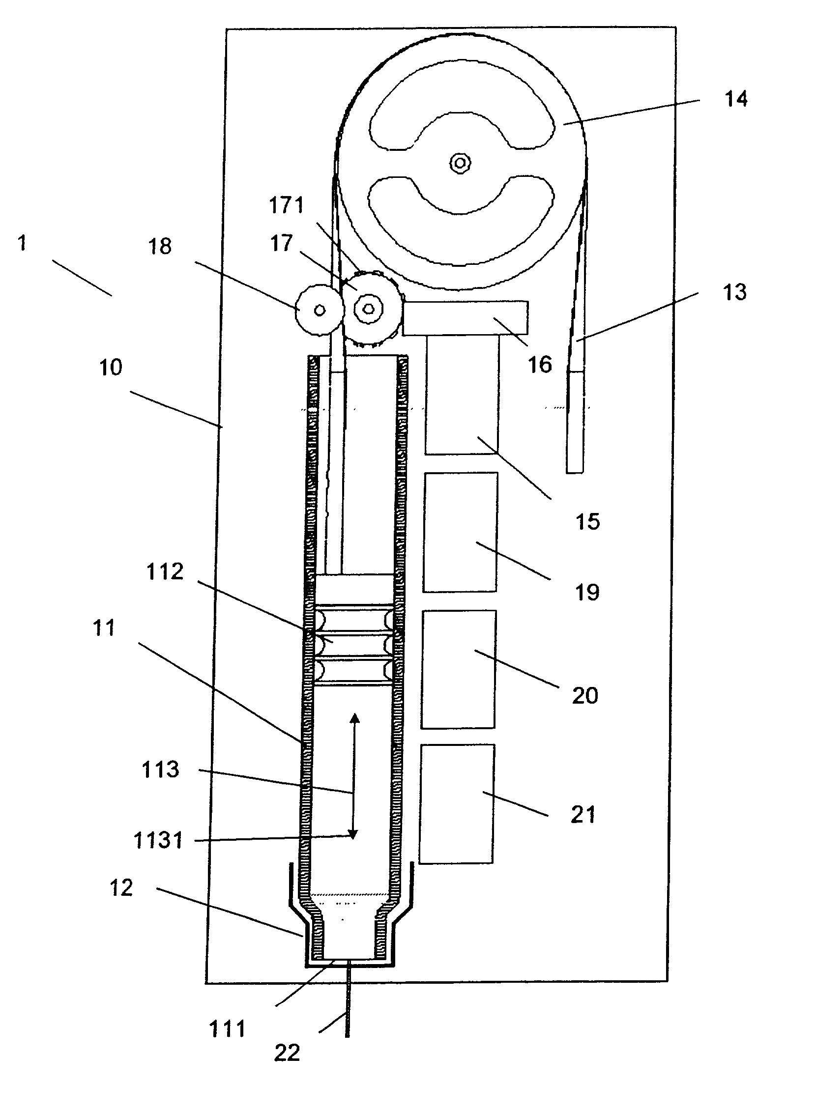
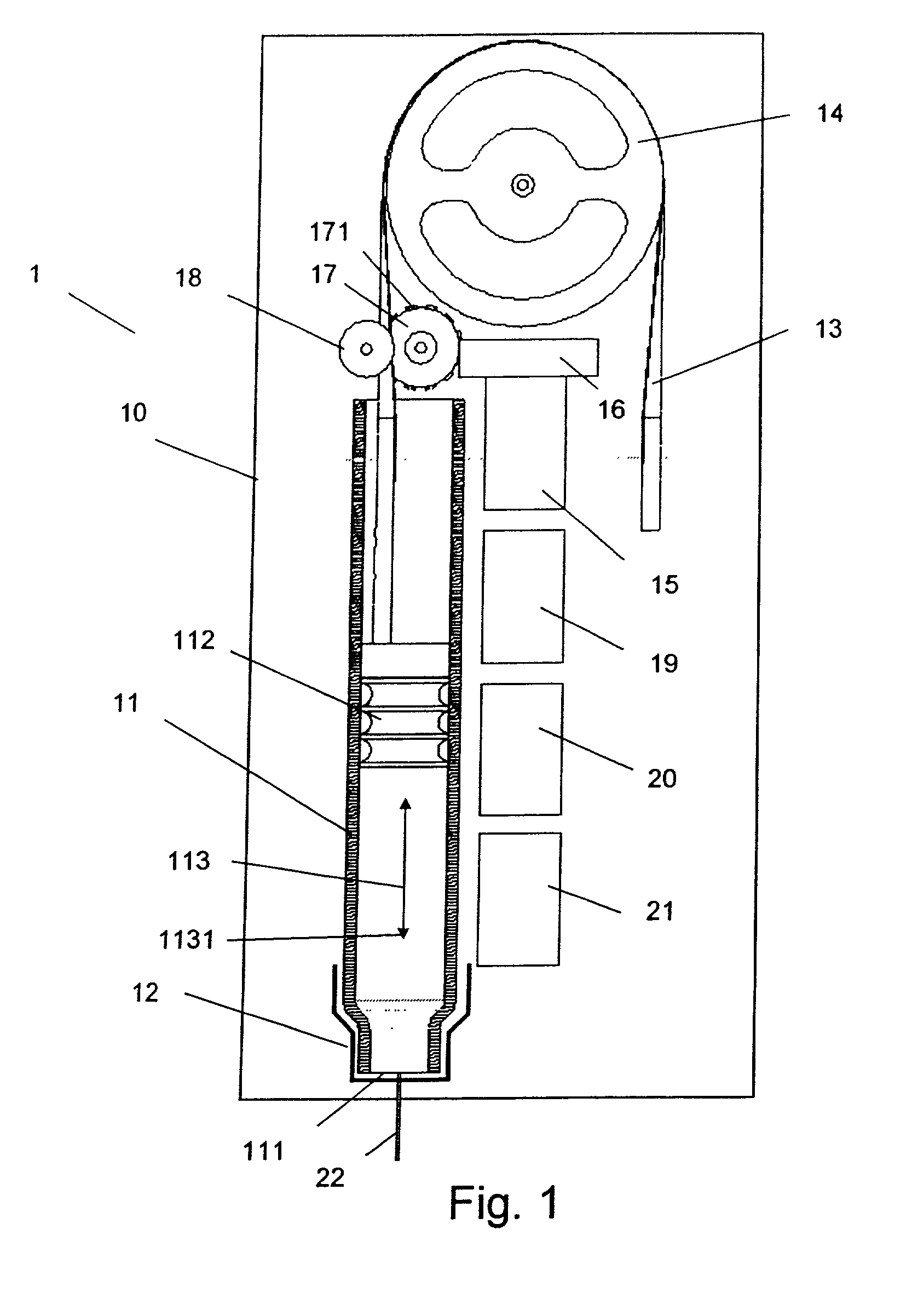
[0053] FIG. 1 shows a medication delivery system according to the invention where the driving wheel is located next to the medication cartridge.

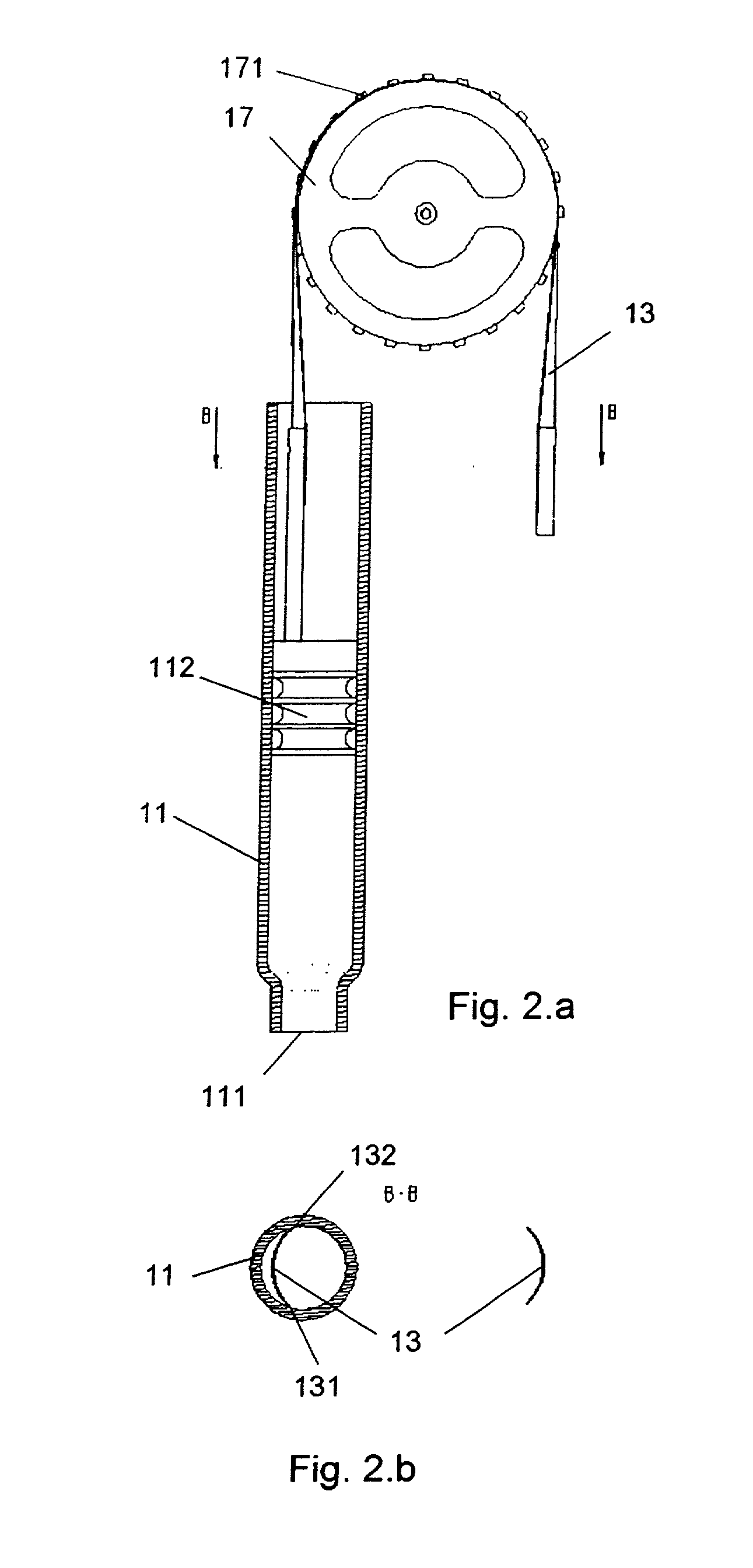
[0054] In the embodiment of the medication delivery system 1 in FIG. 1, a medication cartridge 11 (possibly a replaceable one) with a piston 112 and an outlet 111 to which a needle 22 (possibly replaceable) may be fixed, is shown to cooperate with a piston rod 13 in the form of a tape, the tape being arcuate (cf. correspondingly FIG. 2.b) in a transversal cross-section. The cartridge 11 is removably fixed to a cartridge holder 12. The piston rod 13 may be displaced along a longitudinal axis 113 of the cartridge 11. A downstream direction is defined by the arrow 1131. The movement of the piston rod 13 is activated by an electromotor 15 whose rotational movement is transferred to a linear displacement of the piston rod by suitable driving means, the driving means comprising inter alia a driving wheel 17 with regularly spaced protruding members...


PUM


Abstract

The invention relates to: A portable medication delivery device (1) comprising a medication cartridge (11) having an outlet (111) and a movable piston (112), and a housing (12) for holding said cartridge, and a flexible piston rod (13) being operable to engage and displace said piston along an axis (113) of said cartridge, and guiding means (14) for bending said piston rod away from said axis, and actuating means (15), and driving means (16, 17) for transferring movement from said actuating means to said piston rod, said driving means including a driving wheel (17) for displacing the piston rod (13), said flexible piston rod comprising regularly spaced first members (330; 331; 332) adapted to mechanically cooperate with corresponding second members (171) on said driving wheel. The object of the present invention is to provide a medication delivery system that combines compactness with an improved accuracy. The problem is solved in that said flexible piston rod (13) exhibits a linear or approximately linear path between said driving wheel (17) and said piston (112). This has the advantage of yielding a compact, low-weight device with an improved dose accuracy. The invention may e.g. be used in injection or infusion devices for a person's self-treatment of a disease such as diabetes.

Description

THE TECHNICAL FIELD OF THE INVENTION[0001] The invention relates to the design of medication delivery systems with a view to compactness, reliability, weight and production cost.[0002] The invention relates specifically to: A portable medication delivery device comprising a medication cartridge having an outlet and a movable piston, and a housing for holding said cartridge, and a flexible piston rod being operable to engage and displace said piston along an axis of said cartridge, and guiding means for bending said piston rod away from said axis, and actuating means, and driving means for transferring movement from said actuating means to said piston rod, said driving means including a driving wheel for displacing the piston rod, said flexible piston rod comprising regularly spaced first members adapted to mechanically cooperate with corresponding second members on said driving wheel.DESCRIPTION OF RELATED ART[0003] The following account of the prior art relates to one of the areas ...

Claims


Application Information

Patent Timeline
IPC IPC(8): A61M5/145A61M5/315G01N33/50G01N33/566
CPCA61M5/14566A61M2005/31518B05C17/0113
Inventor KLITMOSE, LARS PETER
Owner NOVO NORDISK AS
Learn More