
Method of laying panels

a technology of mechanical joining and joining panels, which is applied in the direction of building components, roof coverings, walls, etc., can solve the problems of gap between the two joining panels, need of longitudinal displacement of the groove panel, and floor prone to mechanical destruction and water penetration

Inactive Publication Date: 2002-06-13
KRONOSPAN TECHN
View PDF0 Cites 171 Cited by
  • Summary
  • Abstract
  • Description
  • Claims
  • Application Information

AI Technical Summary

Benefits of technology

[0033] Said second angle is adopted to the possibility to displace easily the panels in said third direction, without loosing the locking function of said locking members in said first and second direction.
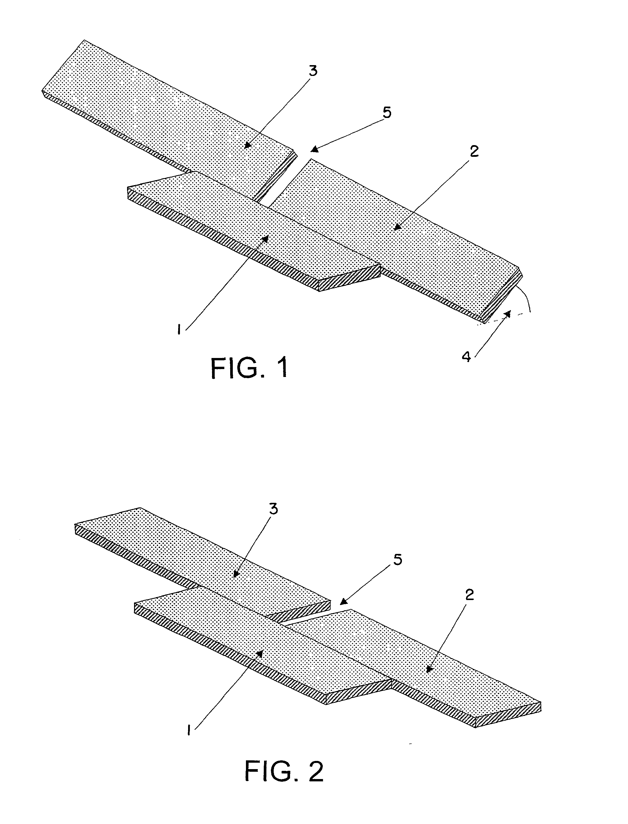
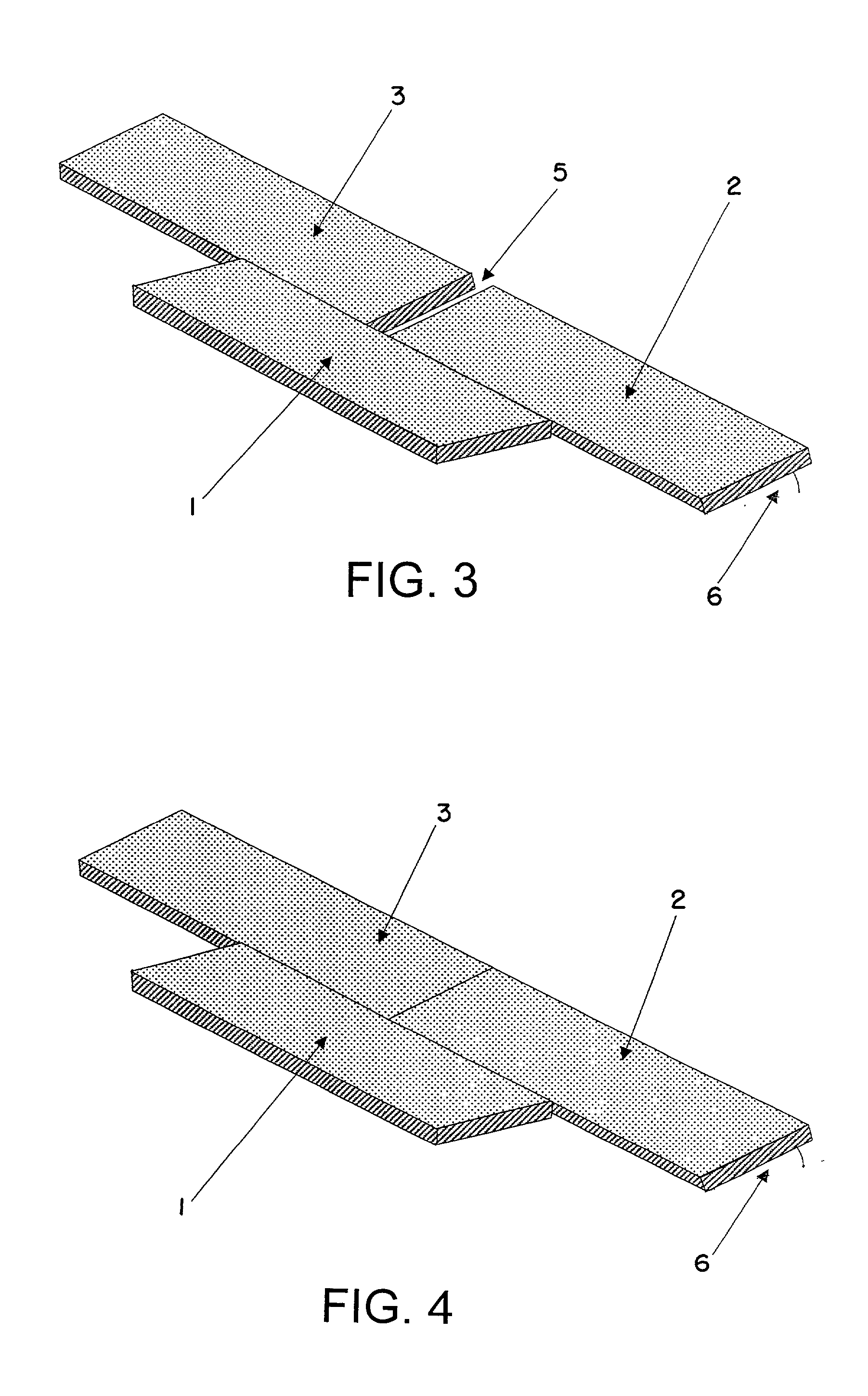
[0036] In a second step the second and third panel are angled into said third mutual position in relation to the first panel. Thereby, said second and third panel each achieve the possibility of easy displacement in said third direction in relation to said first panel.
[0040] The connection between said second and third panel and the locking of this connection is achieved, while those panels are in said third position in relation to said first panel. In said third position a displacement of the panels in relation to each other can be carried out easily. Friction being effective against said displacement is brought to minimum by angling the panels in said second angle. Since the panels are locked in the other directions, a displacement in a third direction, which is in direction of the adjacent joint edges, in relation to each other cannot lead to loss of the connection.
[0042] Using said laying method avoids the need of providing the play known from U.S. Pat. No. 5,706,621 in the joint between the panels, in order to carry out the displacement easily. Avoiding this play can lead to a smooth gapless surface of the laid panels.
[0049] According to a further embodiment, the flanks of said second groove are of the same length. Thereby, it is especially guaranteed, that the panels are locked in said first direction. Further, it is in general easy to provide a panel with said second groove having flanks of the same length by just one shaping action.

Problems solved by technology

The disadvantage of above mentioned laying method lies in the need of displacing the groove panel in its longitudinal direction.
If it is too wide, this play leads to a gap between the two joining panels.
A thus opened joint makes the floor prone to mechanical destruction and penetration of water.
Beside that the look of the laid floor is of poor quality.
Is the play too small, the friction being effective against the longitudinal movement of the connected groove panel is too high.
A force overwhelming this can destroy the panel.
Disadvantage of said laying method is the difficulty in keeping the second and third panel in the common plane position while it is necessary to displace the third panel in the above described way.
Normally, a single person has difficulties to handle this.

Method used


Image

  • Method of laying panels
  • Method of laying panels
  • Method of laying panels

Examples


Embodiment Construction

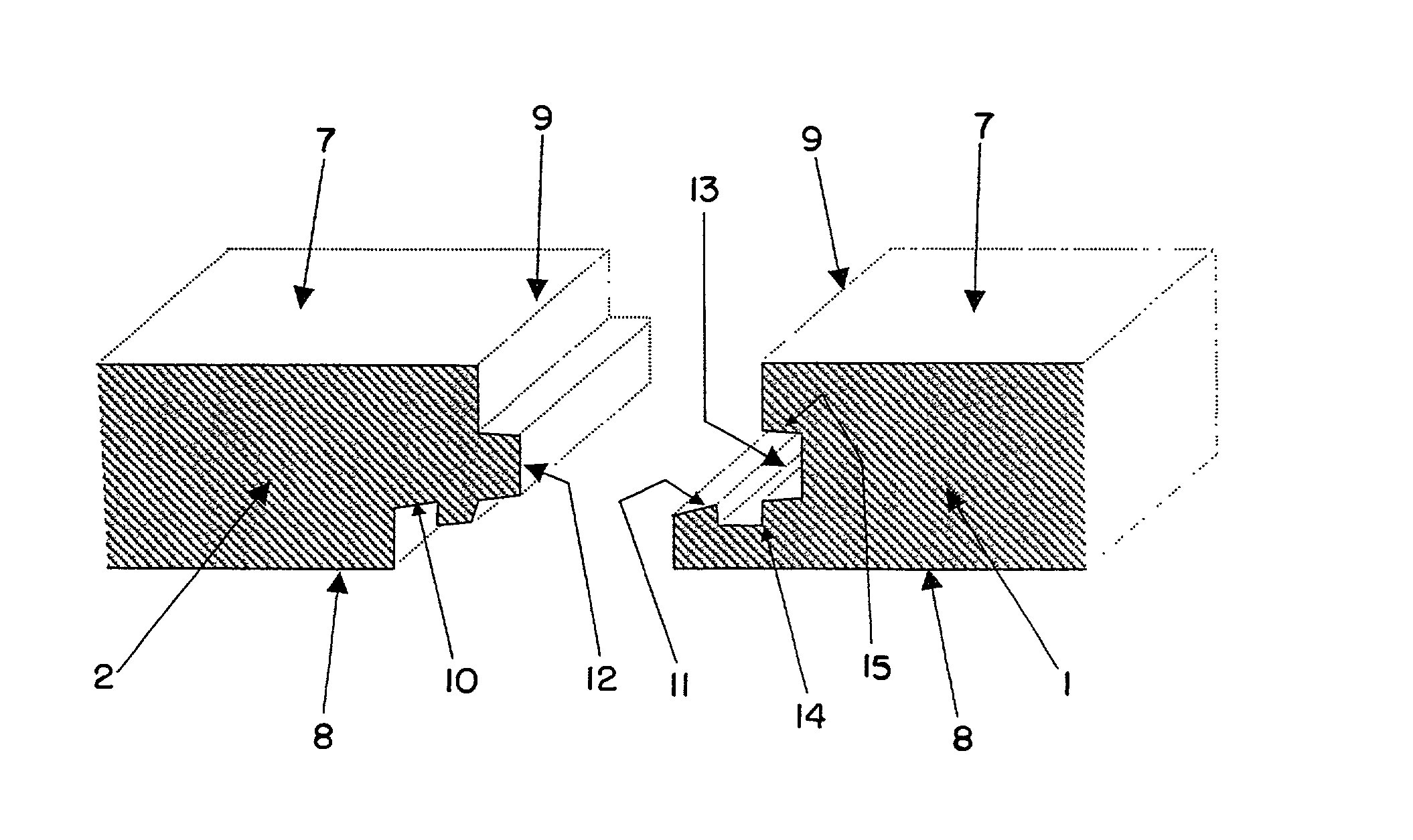
[0065] FIG. 6, to which reference is now made, illustrates a part of a cross-section of a panel 2. At its edge 9 a tongue 12 projects parallel to that edge 9. With its rear side 8 the panel 2 and all further illustrated panels are later in contact with the is floor, the opposite side is its or their surface 7 respectively. A locking groove 10 is part of the tongue 12 and is open at the rear side of the panel 8. As this panel's counterpart a further part of a cross-section of a panel 3 is shown. At its edge 9 it is provided with a second groove 13 with the flanks 14 and 15. Both flanks are of the same length 16. A projection 11 is part of said second groove 13 and projects to said surface 7. In a preferred embodiment of the invention the flank 14, on which said projection 11 is disposed, is flexible.

[0066] FIG. 7, to which reference is now made, illustrates a part of a cross-section of a panel 2. At its edge 9 a tongue 12 projects parallel to that edge 9. A locking groove 10 is part ...


PUM


Abstract

The present invention provides a method of laying and mechanically joining panels, especially floor panels. In a first step a first panel is already located in a first row. A second panel is positioned in a second row in a first position in relation to the first panel. A third panel is now brought into the second row and into the first position in relation to the first panel. In this position, there is a mutual distance between the adjacent edges of the second and third panel. In a second step the second and third panel are angled into the third mutual position in relation to the first panel. Thereby, the second and third panel each achieve the possibility of easy displacement in the third direction in relation to the first panel. In a third step one or both of the second and third panel are moved in relation to the first panel. By this displacement the second and third panel get in a second position in relation to each other. An additional intermediate step may be employed between the first and the second step. In this intermediate step the second and third panel are angled down into the second mutual position in relation to the first panel.

Description

[0001] The invention generally relates to a method of laying and mechanically joining panels providing a joint along adjacent joint edges of two panels, especially floor panels.[0002] More specifically, the joint is of the type where the adjacent joint edges together form a first mechanical connection locking the joint edges to each other in a first direction at right angles to the principal plane of the panels, and where a locking device forms a second mechanical connection locking the panels to each other in a second direction parallel to the principal plane and at right angles to the joint edges. The locking device comprises a locking groove which extends parallel to and spaced from the joint edge of one of the panels, and said locking groove is open at the rear side of this one panel.[0003] The method of laying and mechanically joining is especially well suited for use in joining floor panels. Thus, the following description of the prior art and of the objects and features of th...

Claims


Application Information

Patent Timeline
IPC IPC(8): E04F15/02
CPCE04F15/02E04F2201/026E04F2201/025E04F2201/0153
Inventor LEOPOLDER, CHRISTIAN
Owner KRONOSPAN TECHN
Learn More