Eureka AIR delivers breakthrough ideas for toughest innovation challenges, trusted by R&D personnel around the world.

Organic electroluminescent element

a technology of electroluminescent elements and organic materials, applied in the direction of discharge tube luminescnet screens, natural mineral layered products, transportation and packaging, etc., can solve the problems of poor stability, storage stability and stability, and the stability of charge-transporting materials, etc., to achieve the effect of increasing luminescent intensity and stable characteristics

Inactive Publication Date: 2002-04-11
MINOLTA CO LTD
View PDF0 Cites 22 Cited by
  • Summary
  • Abstract
  • Description
  • Claims
  • Application Information

AI Technical Summary

Benefits of technology

[0016] In light of the aforesaid information, an object of the present invention is to provide an organic electroluminescent element which possesses increased luminescent intensity and exhibits stable characteristics even with repeated use.
[0027] It is believed possible to improve electron injectability by using a mixed layer of magnesium and a metal having a work function greater than magnesium on the negative electrode, and providing a different mixture ratio in the depth direction so as to have an increasing the percentage of metal having a high work function on the exterior side of the negative electrode (i.e., on the opposite side relative to the luminescing layer) produces an extremely smooth electron flow in conjunction with a strong electric field, such that the luminescence starting voltage required to produce luminescence of the organic electroluminescent element of the present invention is adequately reduced and the work function of the negative electrode surface is increased so as to allow stable long-term luminescence by preventing the generation of black spots as well as deterioration caused by oxidation of the negative electrode surface. It is further believed that the negative electrode has superior layer formability due to the excellent layer forming characteristics of magnesium as an alloy, and that the formed element possesses luminescence characteristics of excellent stability due to the relatively excellent stability of the alloy compared to other metals. The present invention is based on the aforesaid knowledge.
[0042] A thicker layer requires a higher application voltage to achieve luminescence, thereby adversely affecting luminous efficiency and causing deterioration of the organic electroluminescent element. Although luminous efficiency improves with a thinner layer, the layer readily breaks down and shortens the service life of the organic electroluminescent element.
[0047] When forming the organic luminescing layer via vacuum deposition, the thickness of said layer is normally 1.about.200 nm, and desirably 1.about.100 nm, whereas when said layer is formed by an application method, the thickness of said layer may be 5.about.500 nm. A thicker layer requires a higher application voltage to achieve luminescence, thereby adversely affecting luminous efficiency and causing deterioration of the organic electroluminescent element. Although luminous efficiency improves with a thinner layer, the layer readily breaks down and shortens the service life of the organic electroluminescent element.
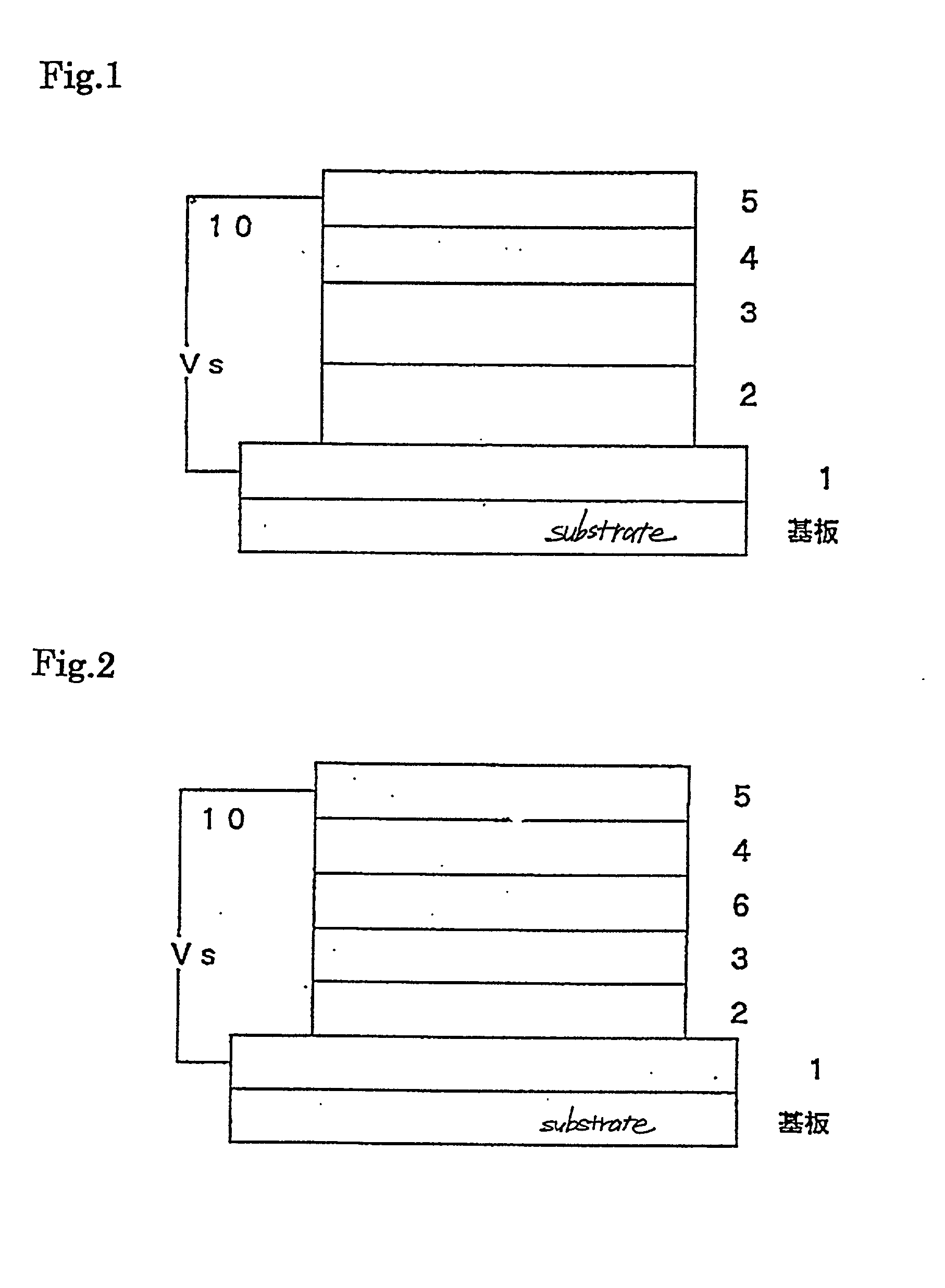
[0052] The electroluminescent element of the construction shown in FIG. 2 differs from the construction of the electroluminescent element of FIG. 1 in that it is provided with an electron injecting / transporting layer 5 interposed between negative electrode 4 and organic luminescing layer 3. The electron injecting / transporting layer is provided to accelerate electron injection and transport.

Problems solved by technology

Although organic electroluminescent elements have high luminance characteristics, they also are unstable when luminescing and have poor stability during storage so as to be impractical for use.
One disadvantage of the aforesaid elements regarding storage stability and stability during luminescence pertains to the stability of the charge-transporting material.
Further disadvantages arise, however when metals other than aluminum are used, inasmuch as the layer formation conditions become more difficult, oxidation may occur during layer formation, black spots become prevalent when luminescing.

Method used


Image

  • Organic electroluminescent element
  • Organic electroluminescent element

Examples


example 2

[0067] A thin hole injecting / transporting layer was formed on a glass substrate coated with indium-tin oxide via vacuum deposition using N,N'-diphenyl-N,N'-bis(3-methylphenyl)-1,1'-diphenyl-4,4'-diamine to form a layer 60 nm in thickness.

[0068] A thin layer of aluminum trisoxine 60 nm in thickness was superimposed over the aforesaid hole injecting / transporting layer via vacuum deposition to form an organic luminescing layer.

[0069] Then, magnesium and silver were co-deposited via vacuum deposition to form a thin layer 50 nm in thickness with an atomic ratio of 10:1 to form a negative electrode. A thin layer of magnesium and silver about 100 nm in thickness was then co-deposited over the aforesaid layer via resistance heating at an atomic ratio of 1:5.

[0070] The organic electroluminescent element was produced in this manner.

[0071] The magnesium used has a work function of 3.66 eV.

[0072] The silver used had a work function of 4.26 eV.

example 3

[0073] A thin hole injecting / transporting layer was formed on a glass substrate coated with indium-tin oxide via vacuum deposition using N,N'-diphenyl-N,N'-bis(3-methylphenyl)-1,1'-diphenyl-4,4'-diamine to form a layer 60 nm in thickness.

[0074] A thin layer of aluminum trisoxine 60 nm in thickness was superimposed over the aforesaid hole injecting / transporting layer via vacuum deposition to form an organic luminescing layer.

[0075] Then, magnesium and indium were vacuum deposited together to form a thin layer 60 nm in thickness with an atomic ratio of 10:1 to form a negative electrode. A thin layer of magnesium and indium about 140 nm in thickness was then co-deposited over the aforesaid layer via resistance heating at an atomic ratio of 1:5.

[0076] The organic electroluminescent element was produced in this manner.

[0077] The magnesium used has a work function of 3.66 eV.

[0078] The indium used had a work function of 4.09 eV.

reference example 1

[0079] An organic electroluminescent element was prepared in the same manner as in Example 1 with the exception that the negative electrode was formed by co-depositing magnesium and silver via resistance heating at an atomic ratio of 10:1 and layer thickness of 100 nm.

[0080] The magnesium used has a work function of 3.66 eV.

[0081] The silver used had a work function of 4.26 eV.


PUM

PropertyMeasurementUnit
thicknessaaaaaaaaaa
work functionaaaaaaaaaa
thicknessaaaaaaaaaa

Abstract

The object of the invention is to provide an organic electroluminescent element which reduces the luminescence starting voltage, increases the luminescence brightness, and has excellent stability with repeated use. The invention achieves these objects by providing an organic electroluminescent element comprising at least a positive electrode, luminescing layer, and negative electrode, wherein said negative electrode is a compound layer of magnesium and a metal having a higher work function than magnesium, and the exterior surface side of said compound layer has a higher percentage of metal having a high work function.

Description

[0001] This application is based on Application No. HEI 9-267036 filed in Japan, the content of which is hereby incorporated by reference.[0002] 1. Field of the Invention[0003] The present invention relates to an organic electroluminescent element.[0004] 2. Description of the Related Art[0005] Organic electroluminescent elements are elements constructed using organic compounds as luminescent materials which emit light in response to electric signals.[0006] Organic electroluminescent elements have a basic structure of an organic luminescent layer interposed between a pair of opposing electrodes.[0007] Electroluminescence is a phenomenon wherein electrons are injected from one electrode and holes are injected from another electrode so as to excite an illuminant within the luminescent layer to a higher energy level, and excess energy is discharged as light when the illuminant returns to its original base state.[0008] In addition to the aforesaid basic structure, a hole injecting layer ...

Claims


Application Information

Patent Timeline
Patent Type & Authority Applications(United States)
IPC IPC(8): H05B33/26C09K11/06H01L51/50H01L51/52H05B33/12
CPCY10T428/24942H01L51/5221Y10T428/31678H10K2101/80H10K50/826H10K50/82
Inventor UEDA, HIDEAKIFURUKAWA, KEIICHITERASAKA, YOSHIHISA
Owner MINOLTA CO LTD
Why Eureka
Eureka Blog
Learn More