
Skin loosening or removal process and apparatus

a skin loosening or removal process technology, applied in the direction of gas current separation, hulling, husking, etc., can solve the problems of affecting the operation of the apparatus, the pre-treatment steps may be undesirable, and the equipment required for such pre-treatments moreover involve considerable extra plant investment costs and maintenance costs, and particular forms of pre-treatment also have their particular associated problems

Inactive Publication Date: 2002-03-14
HAZELCO
View PDF0 Cites 5 Cited by
  • Summary
  • Abstract
  • Description
  • Claims
  • Application Information

AI Technical Summary

Benefits of technology

The process significantly reduces skin removal time, minimizes pre-treatment needs, and maintains product quality by avoiding heat and chemical use, achieving high efficiency and low maintenance with minimal damage to the kernels, allowing for rapid processing of a large quantity of products.

Problems solved by technology

Although necessary in order to attain skinned nuts of the required quality, these pre-treatment steps may thus be undesirable since they add time to the skinning operation as a whole.
The apparatus required for such pre-treatments moreover usually involve considerable extra plant investment costs and maintenance costs.
Particular forms of pre-treatment also have their particular associated problems.
For example, with treatments that involve a nut kernel being heated, the heat so applied can cause damage to the kernel's cell structure, reducing its shelf life and affecting its flavour characteristics.
Also, when heating the nut kernel has only been partially successful in loosening the kernel skin, repeating is not desirable due to the likelihood of damage.
Soaking forms of pre-treatment have the disadvantage that they are typically highly time consuming.
A significant proportion of the nuts may remain unskinned without such pre-treatment.
In order to be sure that there are no nuts above a correctly positioned nut, which would shield that nut from the jets, each nut must effectively be conveyed individually along a chamber during the skinning process and this is inefficient in terms of production rates.
The machine is complicated in that the rotating rolls have to be provided and in that the jets of water have to be carefully aimed to provide the desired glancing blows.
In addition, the rotation of the nuts on the rolls demands, in the main, uniformly spherical and uniformly sized nuts, thereby limiting the types and varieties which can be used in the machine.
Because of the need to abrade the nuts at the floor of the chamber, the nuts have to be conveyed individually along the chamber and there are again limitations in production rates and the ability to deal with products of different shape and size.
It will therefore be generally necessary to load the containment area with only one layer of walnuts and this will again impose a limitation on production rates.
This saves on energy costs.
However, in view of the efficiency of the skin removal process, it will generally be necessary to repeat the method on only a small proportion of the products, if any.
This will tend to result in a different part of each product being presented to the jet or jets on each exposure, whereby substantially all surfaces of the products in the receiving means are exposed over a period of time.
This is beneficial as compared to rotating rolls which require a drive mechanism and may cause undesirable excessive abrasion of the products.
Further, providing two nozzles means that there are two jets of liquid impacting on the products rather than just one, which results in an increased frequency of impact and hence a reduced processing time.

Method used


Image

  • Skin loosening or removal process and apparatus
  • Skin loosening or removal process and apparatus
  • Skin loosening or removal process and apparatus

Examples


first embodiment

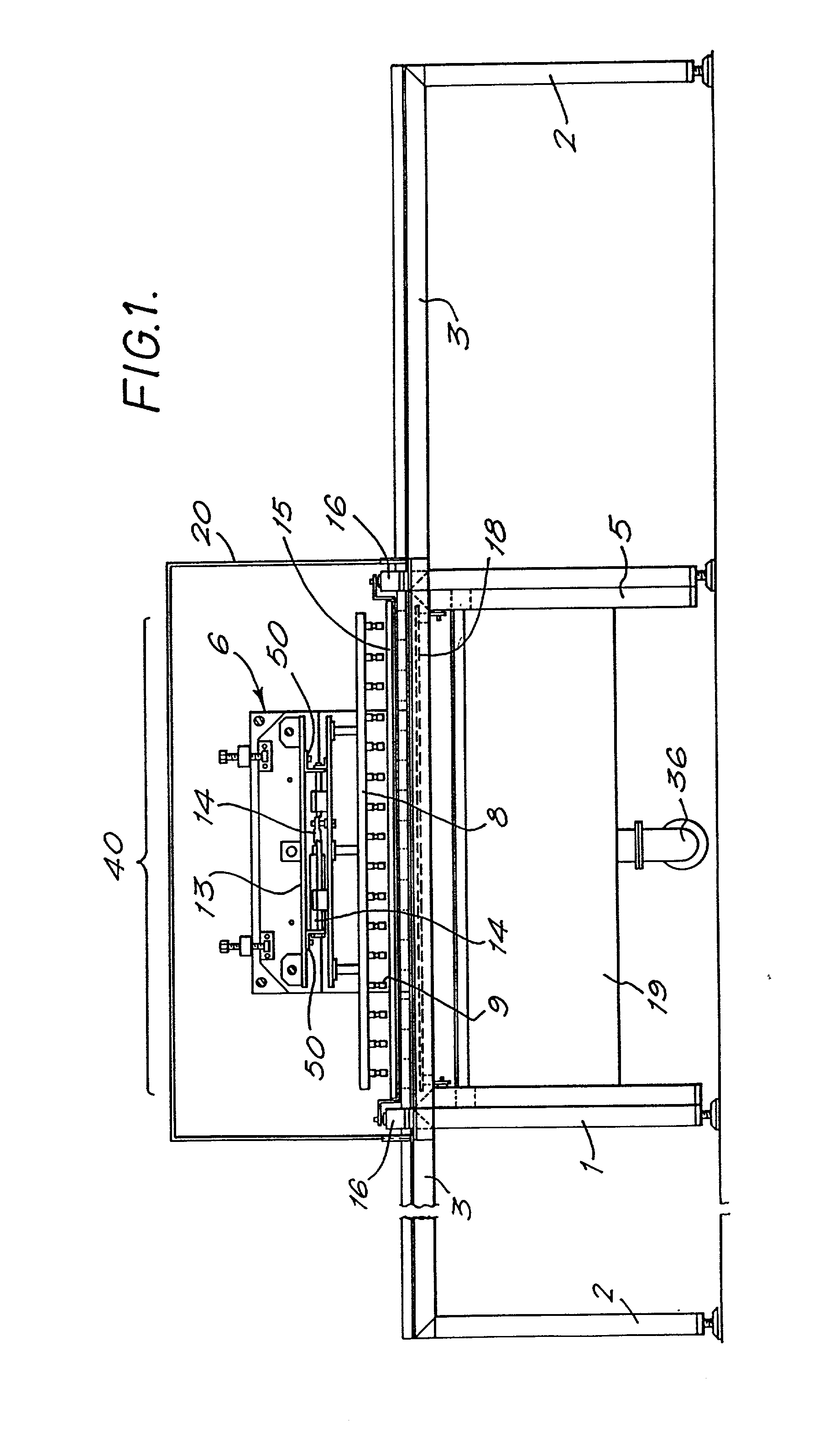
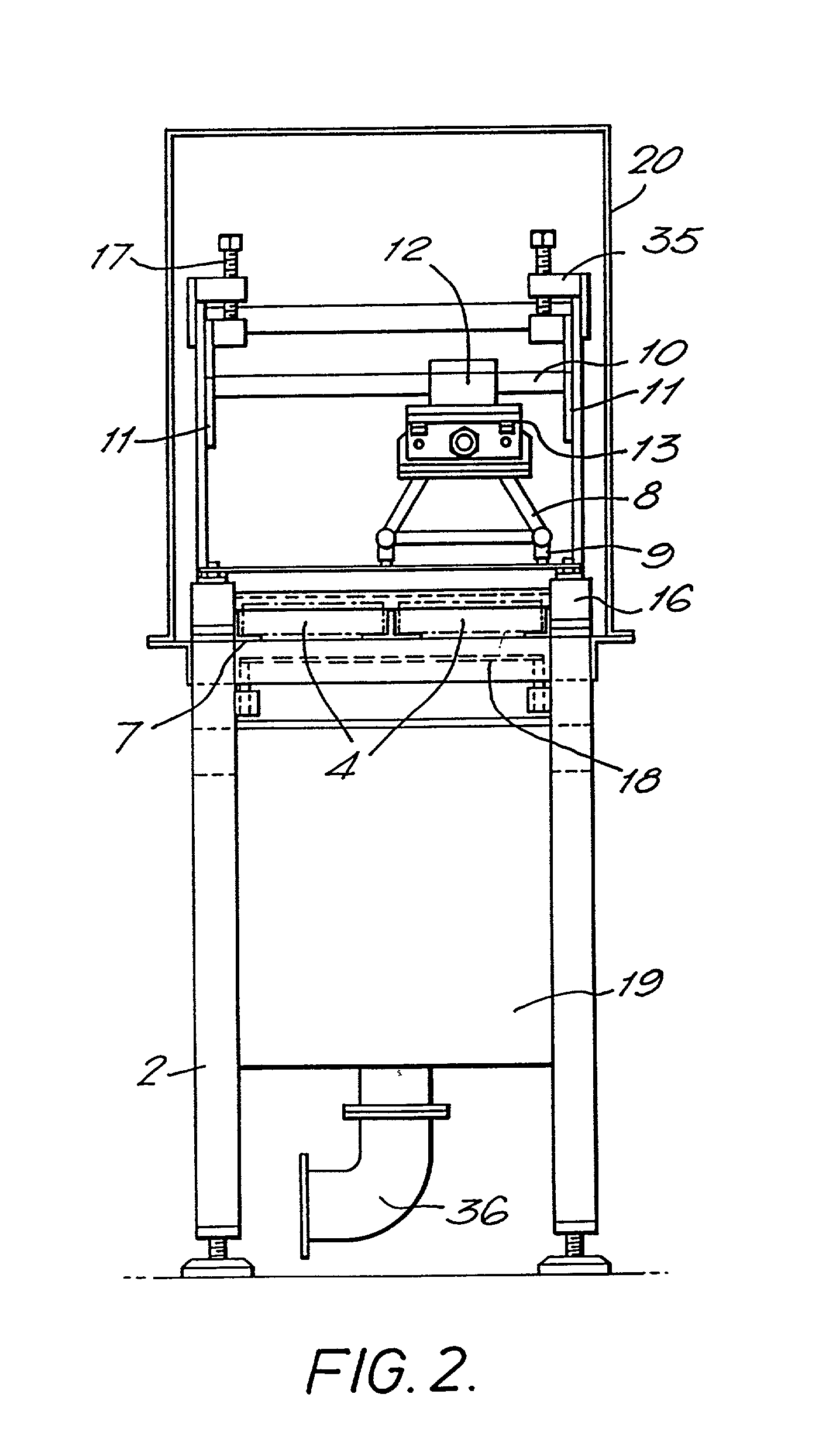
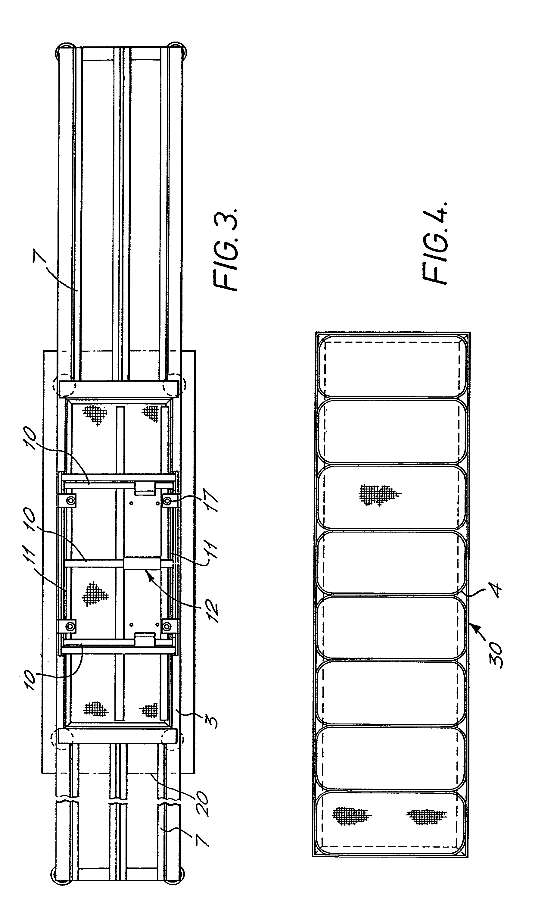
[0073] the apparatus comprises a main frame 1 having four pairs of support legs 2, a platform 3 supported by the legs and receiving four product trays 30 made up of product receiving means in the form of cages 4, and a centre frame 5 mounted between the two pairs of centrally positioned legs and 10 supporting thereon a water supply mechanism 6. The water supply mechanism is arranged above a product processing area 40 defined centrally of the platform 3.

[0074] The frame and tray components are made from stainless steel for its anti-corrosive properties although alternative materials such as other suitable metals or plastics may be used.

[0075] As seen in FIG. 4, each product tray 30 comprises eight cages arranged in a row. Any suitable number of cages may be used, joined together or separate. Two pairs of product trays 30 are provided, the trays of each pair being arranged side by side. The trays are slidably received on rails 7 which extend along the length of the apparatus and whic...

second embodiment

[0091] As is most clearly visible from FIG. 5, the product receiving means in the form of product carriers 150 in the second embodiment are arranged on an endless conveyor chain 152. The conveyor chain loops around two pulleys and follows a forward, upwardly facing path and a return, downwardly facing path. The chain is driven by a drive assembly 154. The receiving means are only shown at one end of the chain for clarity purposes.

[0092] As can be seen from FIGS. 11 to 13, each of the product carriers 150 is in the form of a generally cuboid block, having an annular recess 156 in its upper surface 158 which serves to receive the products. There is an upstanding central region 160 serving to define the radially inner wall of the annular recess 156. The recess and the upstanding central region can also be seen in FIGS. 5 and 7.

[0093] In cross-section, the shape of the recess 156 is generally U-shaped, as shown in FIG. 10. The lower surface 162 of the recess 156 is formed with raised ri...


PUM


Abstract

Apparatus for loosening or removing the skin from products such as nut kernels, beans, seeds or the like. Carriers are arranged to receive the products and a liquid jet manifold is adapted to direct jet or jets at the products. In a preferred embodiment, the products are disposed in an annular recess in a carrier, and are subjected to jets of liquid discharged from two nozzles at each end of a bar arranged to rotate above the recess.

Description

[0001] This application is a divisional of U.S. Pat. Ser. No. 09 / 059,044, which was in turn a continuation-in-part of U.S. Pat. Ser. No. 081451,073, which was in turn a continuation-in-part of International Patent Application No. PCT / GB94 / 02539 designating the USA and published in English with an international filing date of Nov. 18, 1994.[0002] 1. Field of the Invention[0003] The present invention relates to a process and apparatus for loosening or removing the skins from products such as nut kernels, beans, seeds or the like.[0004] 2. Related Art[0005] Various devices employing different techniques are known for removing the skins from such products.[0006] With particular reference to nut kernels, devices are known which scrub, brush or scrape the nut kernels, or use other abrasive type treatments to remove the nut kernel skins. In certain cases, 40% of the treated products still have their skins adhered thereto. It is then necessary electro-optically or manually to sort the produ...

Claims


Application Information

Patent Timeline
Patent Type & Authority Applications(United States)
IPC IPC(8): A23N5/00
CPCA23N5/00
Inventor LEGGE PRENDIVILLE, JOHN EDWARDAXEL AVISON, MALCOLM LOUIS
Owner HAZELCO
Learn More