
Reversible image display medium

Inactive Publication Date: 2002-01-24
MINOLTA CO LTD
View PDF0 Cites 23 Cited by
  • Summary
  • Abstract
  • Description
  • Claims
  • Application Information

AI Technical Summary

Benefits of technology

[0012] Another object of this invention is to provide a reversible image display medium which is capable of forming images with low energy, namely capable of meeting the current demand for reduction in environmental loads.
[0013] A further object of the invention is to provide a reversible image display medium which is capable of displaying images in good contrast.
[0014] A still further object of the invention is to provide a reversible image display medium which is capable of displaying images in high resolution.
[0015] An additional object of the invention is to provide a reversible image display medium which is capable of smoothly providing image display and image erasure, and image rewriting.
[0016] A still another object of the invention is to provide a reversible image display medium which is capable of stably displaying images for a long time.

Problems solved by technology

Due to the relatively low resolution and the light emission from the display, long-time viewing of displayed images may be hard to eyes.
This results in consumption of a large mount of resources.
The printer or the like also consume large amounts of consumable products or materials such as toner, ink or heat transfer sheets.
This is contrary to the current demand for reduction in environmental loads.
If the magnetic particles have a saturation magnetization degree of less than 20 emu / g, a low magnetic force is exerted by the outer magnetic field on the developer particles in the medium, so that the developer can not be efficiently stirred, resulting in a tendency to lower the density of displayed images.
This lowers the efficiency of stirring the developer and reduces the image density.
If the charging performance of the developer particles present in the reversible image display medium is not stabilized, the Coulomb force acting on the developer particles would change, making it impossible to obtain a stable image density.
However, the second type reversible image display medium can confine the volume resistivity of developer particles to the foregoing range, and can inhibit the change of image contrast and image reflection density due to repeated image display, so that images of high quality can be repeatedly displayed for a longer period of time.
If two kinds of frictionally chargeable dry developer particles have a volume resistivity .rho. of more than 1.0.times.10.sup.14.OMEGA..m-ultidot.cm, the charging amount of the frictionally charged developer particles is markedly increased, so that an excessively great Coulomb force is exerted on the developer particles after displaying images, and the images are likely to remain after erasure operation.
Due to these defects, the image density tends to vary in repeated image formation and erasure.
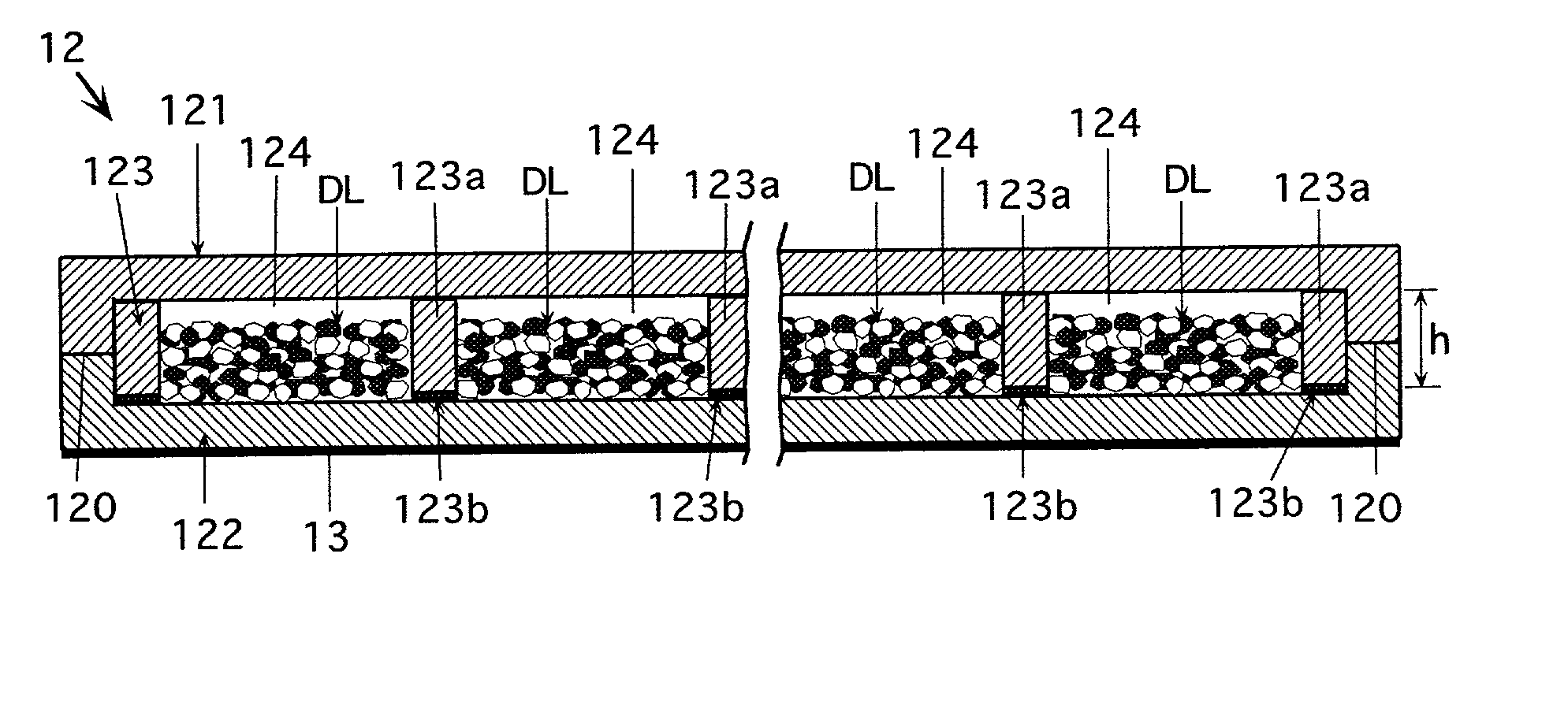
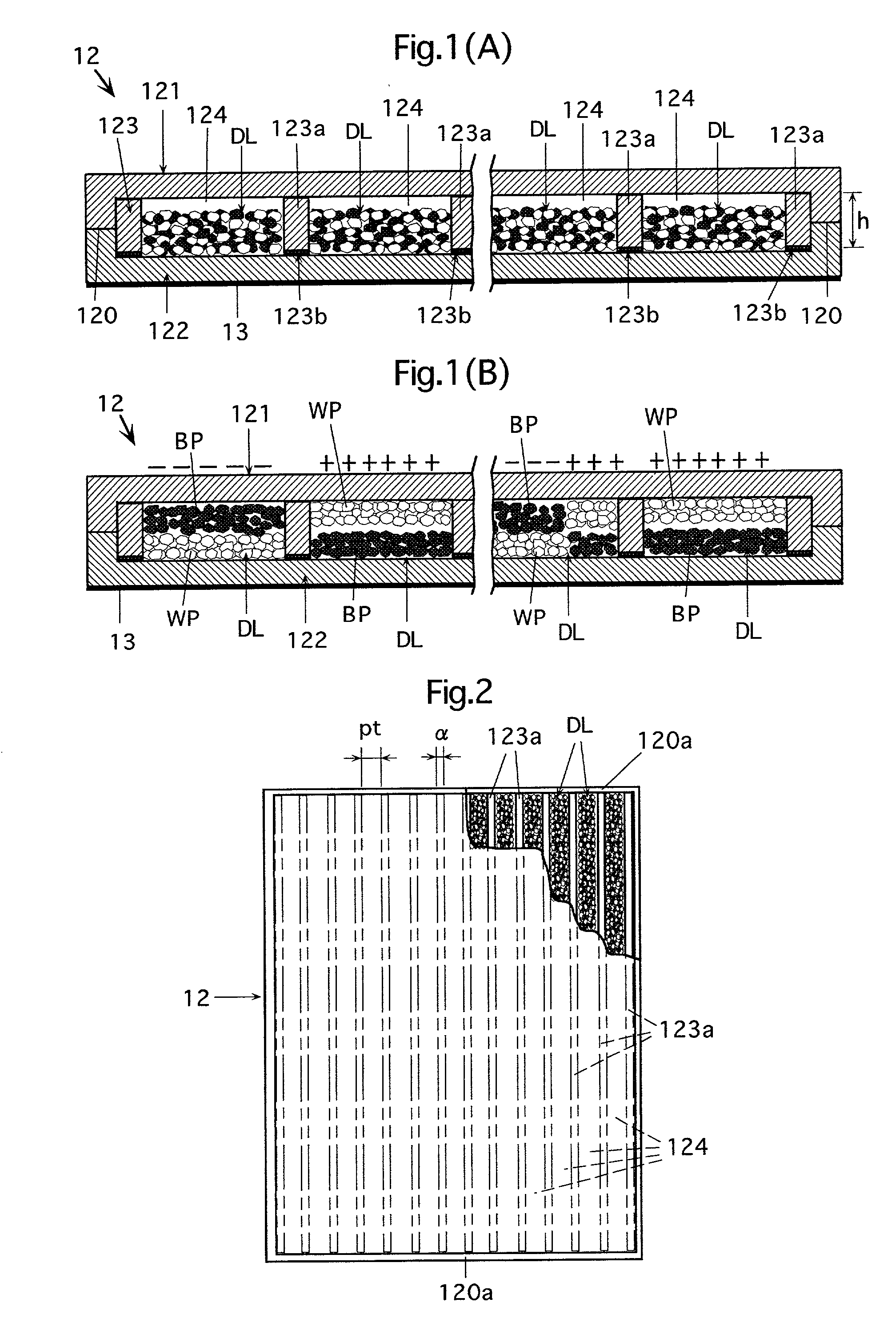
However, each of the partition wall, developer movement suppressing member and the dedicated spacer may be arranged between the substrates without being adhered by the adhesive to one or both of the two substrates, or without being integrated with the substrate, and may be simply arranged to be unmovable with respect to at least one of the substrates.
If the inorganic fine powder is outside the above range in BET specific surface area, a proper fluidity can not be exhibited and a satisfactory developing ability can not be shown.
This raises a problem, for example, that in solid white display, the color (e.g. black) of an underlying layer is seen through a surface white layer.
Further, when the display medium is inclined or shaken, the developer is locally collected, leading to impairment of image quality.
However, each of the partition wall, developer movement suppressing member and the dedicated spacer may be arranged between the substrates without being adhered by the adhesive to one or both of the two substrates, or without being integrated with the substrate, and may be simply arranged to be unmovable with respect to at least one of the substrates.

Method used


Image

  • Reversible image display medium
  • Reversible image display medium
  • Reversible image display medium

Examples


Embodiment Construction

. Ex.: Comparative Example WP: white particles R.D.: reflection density I.D.R.: image density ratio

[0208]

4 TABLE 4 black change .DELTA. Black Magnetic Particles BP Initial portion of volume black R.D. black .sigma. s resistivity portion after portion No. (emu / g) (.OMEGA. .multidot. cm) WP R.D. 100 times R.D. evaluation C. Ex. 3 1 36 1.62 .times. 10.sup.9 WP 1.1 1.05 0.05 X Ex. 4 2 35.9 1.22 .times. 10.sup.10 WP 1.35 1.30 0.05 .largecircle. Ex. 5 3 35.8 9.22 .times. 10.sup.11 WP 1.44 1.38 0.06 .largecircle. Ex. 6 7 35.9 1.62 .times. 10.sup.13 WP 1.45 1.33 0.12 .largecircle. Ex. 7 4 35.8 8.92 .times. 10.sup.13 WP 1.44 1.30 0.14 .largecircle. C. Ex. 4 5 36.2 1.10 .times. 10.sup.14 WP 1.45 1.24 0.21 X C. Ex. 5 6 36 1.10 .times. 10.sup.15 WP 1.5 1.18 0.32 X Ex.: Example C. Ex.: Comparative Example WP: white particles R.D.: reflection density

[0209] As apparent from Table 3, if the saturation magnetization degree of the magnetic developer particles is less than 20 emu / g or more than 50 emu...


PUM


Abstract

This invention provides a reversible image display medium comprising two substrates opposed to each other with a predetermined gap therebetween, one or more developer-accommodating cells formed between the two substrates, and a dry developer accommodated in each cell, in which the dry developer contains at least two kinds of frictionally chargeable dry developer particles having different chargeable polarities and different optical reflection densities, the reversible image display medium having at least any of the following features: (1) at least one kind of the developer particles being magnetic particles containing a binder resin having a magnetic substance incorporated therein, the magnetic particles having a saturation magnetization degree in the range of 20 emu / g to 50 emu / g; (2) at least one kind of the dry developer particles has a volume resistivity rho in the range of 1.0x10¹⁰OMEGA.cm to 1.0x10¹⁴OMEGA.cm; (3) the dry developer contains inorganic fine powder as a fluidization agent, the inorganic fine powder having a BET specific surface area of 80 m2 / g to 300 m2 / g; and (4) the dry developer is accommodated in the cell in an amount of 20 vol. % to 50 vol. % based on the volume of the cell.

Description

[0001] The present invention is based on patent applications Nos. 2000-173088 Pat., and 2000-173091 Pat. filed in Japan, the contents of which are hereby incorporated by reference.[0002] 1. Field of The Invention[0003] The present invention relates to an image display medium and more particularly to a reversible image display medium capable of rewriting the images (namely allowing formation, erasure and rewriting of images).[0004] 2. Description of The Background Art[0005] At present, the text, graphics or the like produced by a computer, a word processor or the like is displayed on a display such as a CRT display, or is output on a medium such as a paper sheet via a printer for display.[0006] The images displayed by a display such as a CRT display show a low resolution, and the resolution, clarity and precision of images are restricted, as compared with the images displayed by the printer or the like on the paper medium or the like. Due to the relatively low resolution and the ligh...

Claims


Application Information

Patent Timeline
IPC IPC(8): G02F1/167G02F1/1671G02F1/1673G02F1/16753G02F1/1685
CPCG02F1/167G02F1/16753G02F1/1673G02F1/1671G02F2001/1678G02F1/1685
Inventor MIYAMOTO, HIDETOSHIYOGOME, KEYAKIMATSUURA, MASAHIKOMIZUNO, HIROSHIKURITA, TAKAJI
Owner MINOLTA CO LTD
Learn More