
Polarization light splitting film, backlight system and liquid crystal display

a technology of polarized light and backlight, applied in the field of light splitters, can solve the problems of degrading display quality, narrow viewing angle in conventional lcds, previously considered disadvantage, and recent improvement,

Inactive Publication Date: 2002-01-10
DAI NIPPON PRINTING CO LTD
View PDF0 Cites 48 Cited by
  • Summary
  • Abstract
  • Description
  • Claims
  • Application Information

AI Technical Summary

Problems solved by technology

Moreover, a narrow viewing angle in conventional LCDs, which was previously considered to be a disadvantage, has been recently overcome by newly developed LCDs with a wide viewing angle.
Approximately half of the incident light is absorbed at the polarizing plate and, accordingly, the efficiency in light usage is low.
However, increasing the light intensity causes a variety of problems, such as increased power consumption of the light source and adverse effects on the liquid crystal material due to heat generated from the thus powered up light source, which degrades the display quality.
The structure of such an illumination system requires a large amount of space.
Therefore, it cannot be applied to thin panel-type LCD devices.
However, the structure of the polarized light splitting layer becomes complicated.
In particular, it is difficult to fabricate the polarized light splitter layer on the inclined sides of the columnar prism array.
This type of backlight system is therefore not suitable for mass production.
However, it is difficult to manufacture such a light scattering conductor with a desirable light scattering performance.
Accordingly, this system is not suitable for actual use.
Therefore, these systems require a complicated structure and are not suitable for mass production.
Furthermore, to produce a sufficient polarization light splitting property using the conventional multi-layer structures above, at least five layers need to be laminated, resulting in a complicated layer structure.
In addition, the polarization light splitting property depends on the incident angle and the wavelength, etc., imposing many undesirable limitations in the actual use.
This is not consistent with a recent trend towards reducing the thickness of LCD devices.
In addition, the conventional polarization light splitting devices would not be effective unless the coupling of the light splitting devices with other elements of the backlight system, such as a diffusion film and a prism sheet, is optimized.
However, there have been no such proposals.
In any event, the conventional backlight systems are limited in the sense that they use the Brewster law (Brewster's law).

Method used


Image

  • Polarization light splitting film, backlight system and liquid crystal display
  • Polarization light splitting film, backlight system and liquid crystal display
  • Polarization light splitting film, backlight system and liquid crystal display

Examples


tenth to fourteenth working examples

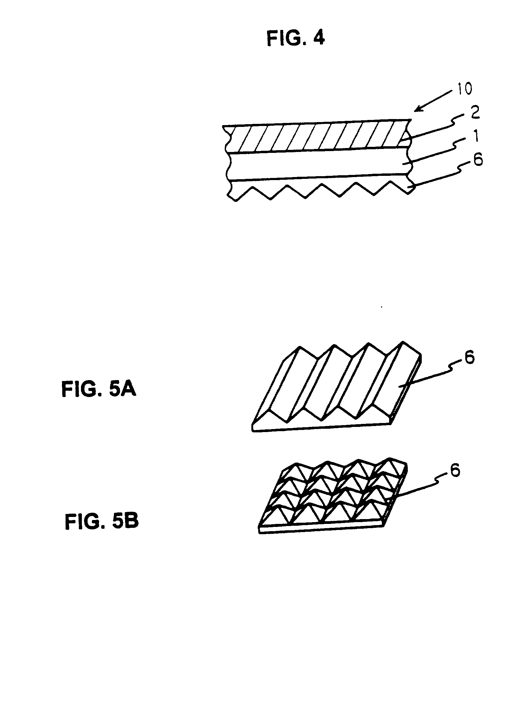
[0123] In these working examples, film bases having uneven surface profiles corresponding to the fifth to ninth working examples above were manufactured by a different method. The tenth to fourteen working examples respectively correspond to the fifth to ninth working examples.

[0124] In these working examples, instead of using embossment, an ultraviolet setting resin was used to form the uneven surface profiles of the film bases corresponding to the fifth to ninth working examples. A urethane resin system primer was applied on a polyethyleneterephtalate film with a thickness of 100 .mu.m and was thermally cured to form a primer layer with a thickness of 1 .mu.m on the polyethyleneterephtalate film.

[0125] An ultraviolet setting resin solution with an epoxy acrylate system as the primary component was coated on the corresponding rotating intaglio roll. Then, the composite film obtained above was pressed onto the intaglio roll with the ultraviolet setting solution and irradiated with u...

working example

FIFTEENTH WORKING EXAMPLE

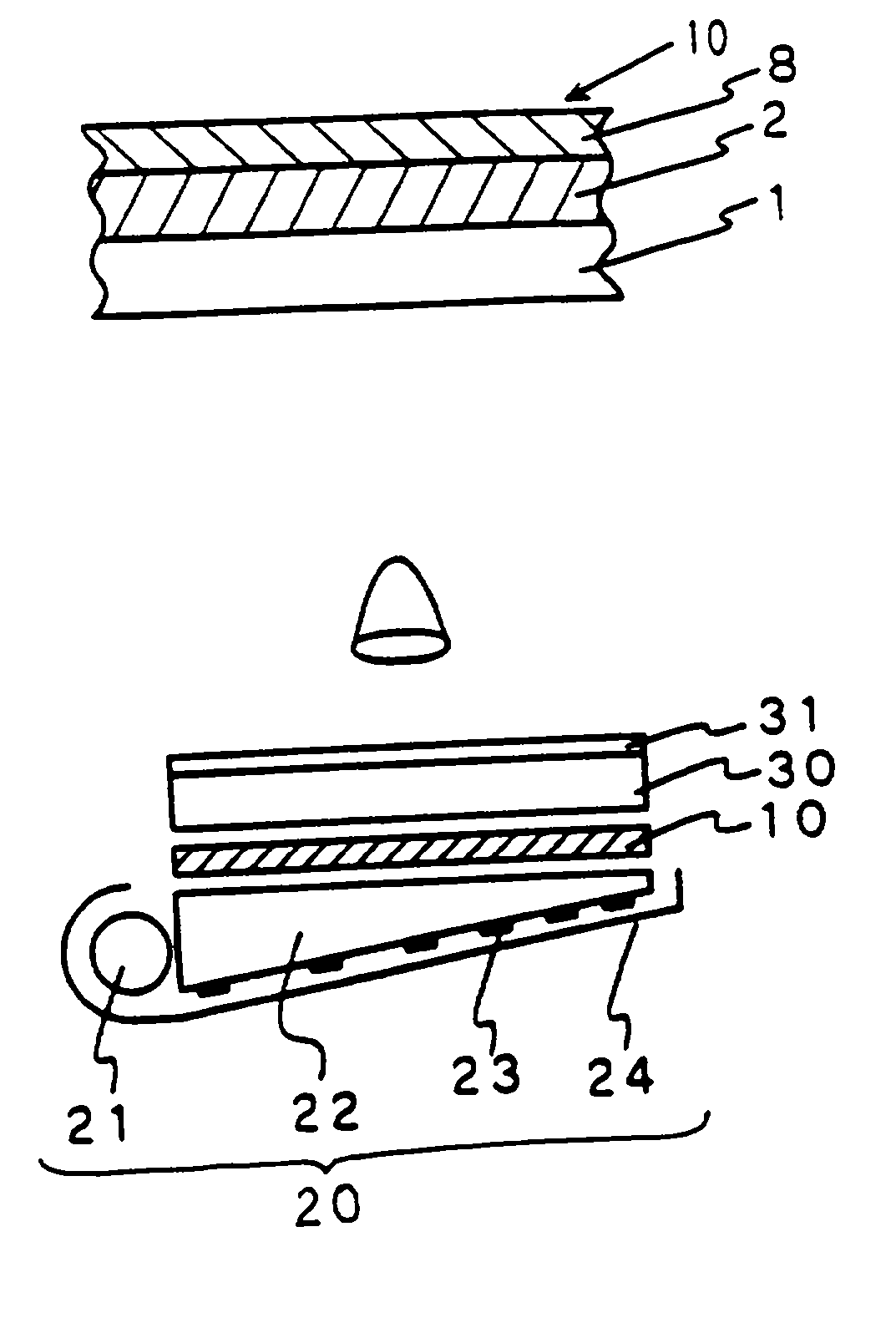
[0126] A polarizing film with a thickness of 120 .mu.m (made by Sumitomo Chemical Co., Ltd., product name, "SUMILITE") was adhered on the quarter-wave layer of the second working example above (i.e., on the light emitting side). See FIG. 8B for the structure.

[0127] Evaluations

[0128] The transmissivity of polarized light, haze, and the luminance of the backlight were measured using the following methods. The results are listed in Tables 1 and 2.

[0129] (1) The polarized light transmission factor: the degree of the polarization linearity in the linearly polarized beam obtained by each of the polarization light splitting films of the above working examples first to fifteen are evaluated in terms of the polarized light transmission factor. FIG. 14 shows the device arrangement used for the measurement. An unpolarized light beam from a light source 51 is transformed into a parallel beam through a lens 52. The parallel beam is incident normally on a polarization lig...


PUM


Abstract

A polarization light splitting film having a light receiving side and a light transmitting side. The polarization light splitting film includes an optical rotation selection layer at the light receiving side for reflecting one of right and left circularly polarized components of a light beam that is incident on the light receiving side and for transmitting the other one of the right and left circular polarization components of the light beam, and a quarter-wave layer laminated over the optical rotation selection layer at the light transmitting side.

Description

[0001] This application claims the benefit of Japanese Application No. 09-48562, filed on Feb. 18, 1997, which is hereby incorporated by reference.[0002] BACKGROUND OF THE INVENTION[0003] 1. Field of the Invention[0004] The present invention relates to a light splitter and, more particularly, to a polarization light splitting film for use in a liquid crystal display device and the like.[0005] 2. Discussion of the Related Art[0006] Due to recent technological development, liquid crystal displays (LCDs) are becoming increasingly popular for use in the display component of a personal computer and the like. Advantages of the liquid crystal display, such as the fact that they are thinner and lighter than the conventional display devices, for example, largely contributed to their gain in popularity. Moreover, a narrow viewing angle in conventional LCDs, which was previously considered to be a disadvantage, has been recently overcome by newly developed LCDs with a wide viewing angle. Accor...

Claims


Application Information

Patent Timeline
IPC IPC(8): G02B5/30G02B27/28G02F1/1335G02F1/13357G02F1/13363
CPCG02B5/3016G02F1/133502G02F1/133504G02F1/133526G02F1/133536G02F1/133615G02F1/13362G02F2001/133543G02F2001/133607G02F2001/133638G02F2201/343G02F1/133543G02F1/133638G02F1/133607G02F1/1335
Inventor ARAKAWA, FUMIHIROKASHIMA, KEIJI
Owner DAI NIPPON PRINTING CO LTD
Learn More