
Diamond coated tool and method of manufacturing the diamond coated tool

a technology of diamond coating and diamond coating, which is applied in the field of diamond coating tools, can solve the problems of increasing the manufacturing cost of tools, deteriorating the durability of coating, and difficulty in obtaining the required degree of smoothness on the machined surfa

Inactive Publication Date: 2002-01-03
OSG
View PDF0 Cites 22 Cited by
  • Summary
  • Abstract
  • Description
  • Claims
  • Application Information

AI Technical Summary

Benefits of technology

[0009] It is a second object of the present invention to provide a method of manufacturing a diamond-coated tool which is capable of machining a workpiece high degrees of surface smoothness and profile accuracy. This second object may be achieved according to any one of sixth, seventh, eighth, ninth and tenth aspects of this invention which are described below.
[0016] The diamond-coated tool defined in any one of the first, second and third aspects of the invention provides a surface of a workpiece machined by the tool, with a high degree of surface smoothness, owing to reduced pits and projections, i.e., reduced irregularities on the outer surface of the diamond coating which is constituted by the diamond crystals each having the diameter not larger than 2 .mu.m as measured on the outer surface of the diamond coating. The diamond-coated tool defined in the third aspect of the invention has an additional advantage that the diameter of each diamond crystal can be easily reduced owing to the multilayer diamond coating consisting of the plurality of layers superposed on each other. It is noted that the term "crystallites" used in this specification is interpreted to mean ones of the crystals each of which has the maximum diameter and length (the largest dimension as measured in the direction substantially perpendicular to the expanding direction of the diamond crystal and the largest dimension as measured in the expanding direction of the diamond crystal) not larger than about 3 .mu.m.
[0020] The diamond-coated tool of this fourth aspect of the invention also provides a surface of a workpiece machined by the tool, with a high degree of surface smoothness, owing to reduced pits and projections in the outer surface of the multilayer diamond coating which is constituted by the diamond crystals each having the length not larger than 2 .mu.m as measured in the expanding direction of the diamond crystal, i.e., in a direction substantially perpendicular to the surface of the substrate.

Problems solved by technology

The large pits and projection on the diamond coating surface are inevitably transferred onto a machined surface of a workpiece which is machined by the cutting tool, thereby making it difficult to obtain a required degree of smoothness on the machined surface.
However, the grinding operation leads to an increase in a manufacturing cost of the tool, and provides a possibility that the diamond coating is damaged by a shock applied to the tool during the grinding operation, thereby possibly deteriorating a durability of the coating.
Further, where the surface of the substrate is roughened to have pits and projections serving to increase an adhesion strength with which the diamond coating adheres to the substrate, the pits and projections, i.e., irregularities on the roughened surface of the substrate are not offset by the diamond crystallites, whereby the pits and projections formed on the substrate surface undesirably remain more or less on the coating surface, resulting in an unsatisfactory degree of smoothness of the coating surface.
The cutting edge of the tool is rounded or chamfered in the roughening operation, whereby the cutting sharpness or performance of the tool is deteriorated.
The deterioration of the cutting sharpness or performance also constitutes a factor causing the deterioration of the machined surface of the workpiece.
The above-described drawbacks or problems are encountered not only where the diamond-coated tool takes the form of a cutting tool but also where the diamond-coated tool takes the form of other machining tool such as a cold-forming tool which is designed to form the workpiece into a desired shape by plastically deforming the workpiece.
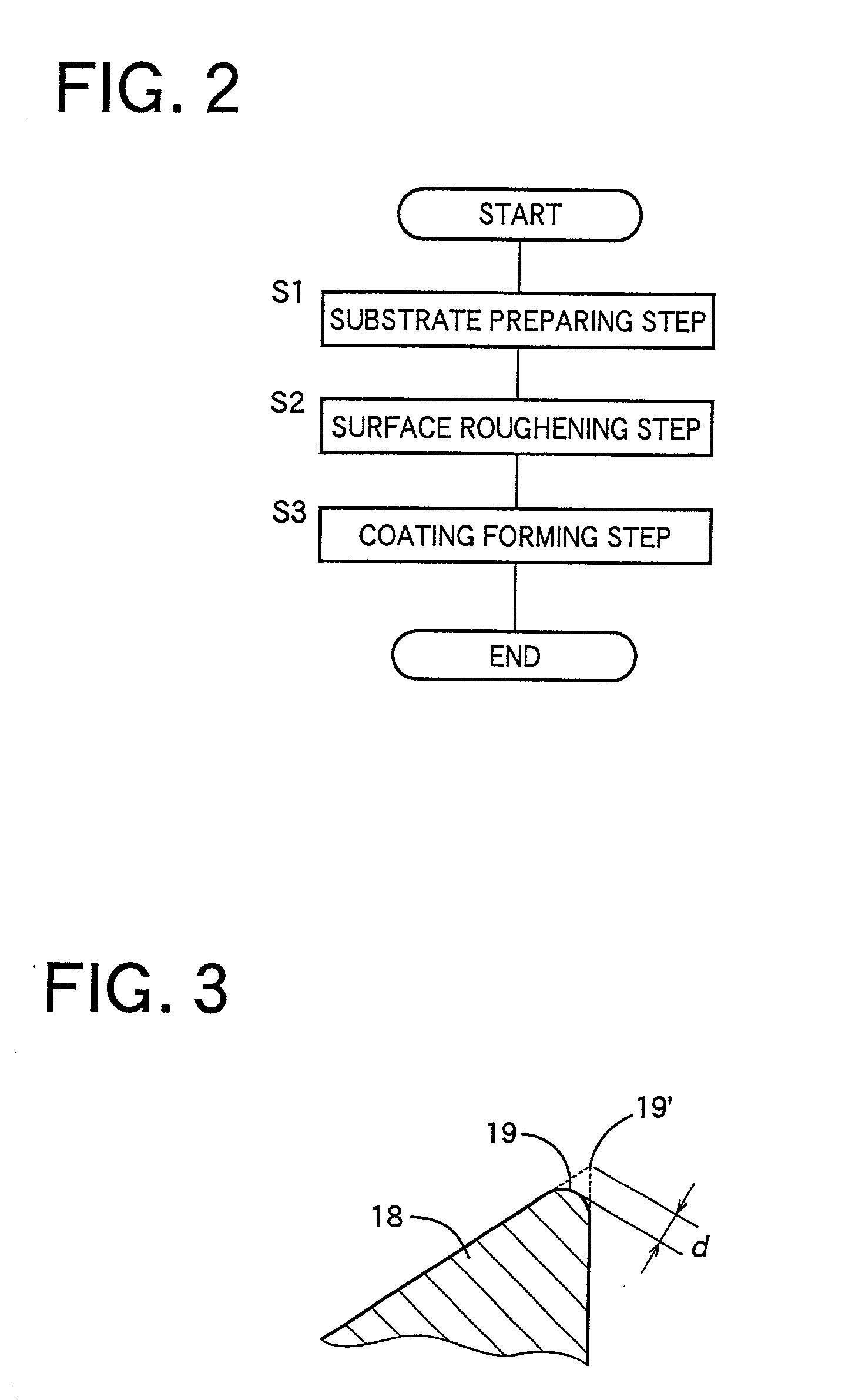
If the displacement amount of the cutting edge as a result of the rounding or chamfering of the cutting edge is larger than 5 .mu.m, the cutting sharpness of the tool is deteriorated.
If the maximum height Ry is larger than 1 .mu.m, or if the ten-point height of irregularities is larger than 0.5 .mu.m, the smoothness in the outer surface of the diamond coating is deteriorated due to the large irregularities in the roughed surface of the substrate, resulting in an unsatisfactory degree of smoothness of the surface of the machined workpiece.
If the ten-point height of irregularities is smaller than 0.2 .mu.m, on the other hand, it is difficult to reliably obtain a sufficiently high degree of adhesion strength with which the diamond coating adheres to the substrate.

Method used


Image

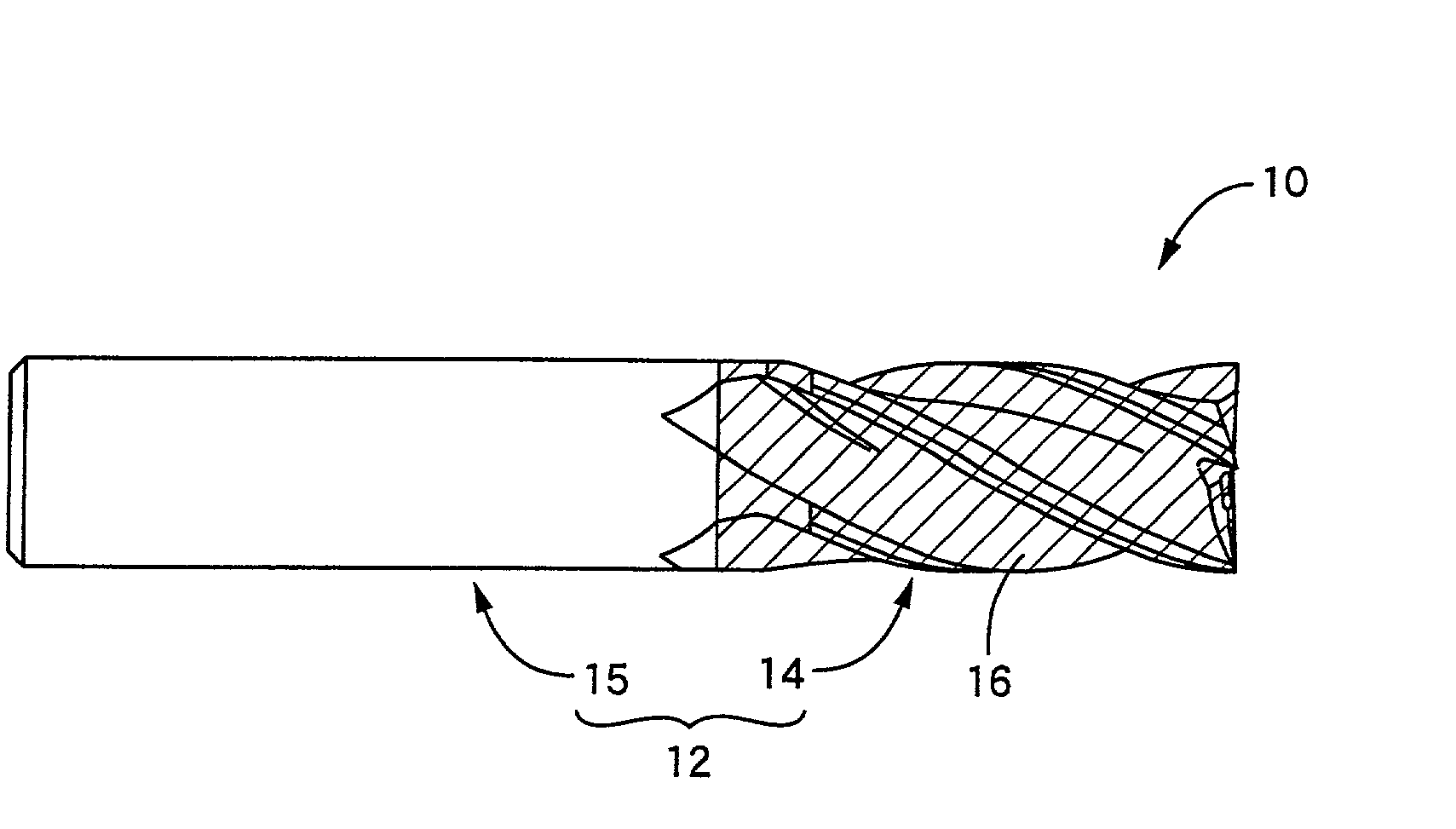
  • Diamond coated tool and method of manufacturing the diamond coated tool
  • Diamond coated tool and method of manufacturing the diamond coated tool
  • Diamond coated tool and method of manufacturing the diamond coated tool

Examples


Embodiment Construction

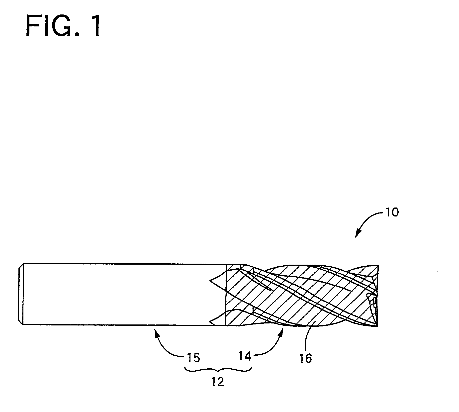
in the form of a diamond-coated end mill constructed according to the present invention; (b) Comparative Example 1 in the form of a non-coated end mill in which the tool substrate is not coated with a coating; (c) Comparative Example 2 in the form of a conventional diamond-coated tool; and (d) Comparative Example 3 in the form of a conventional diamond-coated tool. Described more specifically, Example 1 was prepared in accordance with the procedure illustrated by the flow chart of FIG. 2 such that the surface of the tool substrate was roughened in the surface roughening step S2 to have the maximum height Ry of 1 .mu.m and the ten-point height of irregularities Rz of 0.2-0.5 .mu.m. Comparative Example 1 was prepared without the implementations of the steps S2 and S3 of FIG. 2, and has the tool substrate whose surface has the maximum height Ry smaller than 0.5 .mu.m and the ten-point height of irregularities Rz smaller than 0.2 .mu.m. Comparative Example 2 was prepared by roughening t...


PUM

PropertyMeasurementUnit
Lengthaaaaaaaaaa
Diameteraaaaaaaaaa

Abstract

A diamond-coated tool including: (a) a substrate; and (b) a diamond coating disposed on the substrate. The diamond coating is formed of diamond crystals grown on the substrate. Each of the diamond crystals has a diameter not larger than 2 mum as measured on an outer surface of the diamond coating, and / or a length not larger than 2 mum as measured in a direction in which each of the grown diamond crystals has expanded by its growth. The diamond coating preferably consists of a plurality of layers.

Description

[0001] 1. Field of the Invention[0002] The present invention relates in general to a diamond-coated tool, and more particularly to such a diamond-coated tool which is capable of machining a workpiece with high degrees of surface smoothness and profile accuracy, and also to a method of manufacturing the same.[0003] 2. Discussion of the Related Art[0004] As one type of a cutting tool such as an end mill, a drill, a tap and a disposable or throwaway insert, there is proposed a diamond-coated tool in which a tool substrate is coated with a diamond coating, as disclosed in JP-B2-2519037 (publication of Japanese Patent issued in 1996) by way of example. In the tool disclosed in this Japanese Patent publication, the tool substrate is coated with the diamond coating in accordance with CVD (chemical vapor deposition) method.[0005] The diamond coating of the disclosed tool consists of an aggregation of diamond crystals, each of which has grown or expanded from a nucleus disposed on the surfac...

Claims


Application Information

Patent Timeline
IPC IPC(8): B23C5/16B23B27/14B23B27/20B23B51/00B23C5/10B23P15/28C23C16/02C23C16/27C23C16/511
CPCB23B2226/31B23C5/10B23C2210/126C23C16/0227Y10T407/27C23C16/279Y10T407/1946Y10T428/30C23C16/274
Inventor HANYU, HIROYUKI
Owner OSG
Learn More