High efficiency converter for zero voltage switching

Inactive Publication Date: 2001-10-25
SAMSUNG ELECTRO MECHANICS CO LTD
View PDF0 Cites 16 Cited by
  • Summary
  • Abstract
  • Description
  • Claims
  • Application Information

AI Technical Summary

Benefits of technology

[0019] This invention is devised to solve the above problem matter whose purpose is to provide high efficiency converter for ZVS combining both side advantages of traditional active clamp flyback circuit and asymmetric flyback circuit to reduce drain-source voltage of switch (MOSFET), enhance adapter efficiency, and make the input voltage doubler circuit be not needed by means of making the converter to act in ZVS in wide range of whole input voltage.

Problems solved by technology

And there occurs disadvantage that drain-source voltage of FET used for switching element in the above active clamp flyback circuit is clamped to substantially high voltage adding the input voltage and the clamp capacitor voltage together.

Method used


Image

  • High efficiency converter for zero voltage switching
  • High efficiency converter for zero voltage switching
  • High efficiency converter for zero voltage switching

Examples


Embodiment Construction

[0029] Various merits and purpose of this invention as described above will be more manifested for persons skilled in this technical field according to preferable practice example of this invention explained hereafter with reference to appended drawings.

[0030] Now the preferable practice example of this invention is explained in detail as follows with reference to appended drawings.

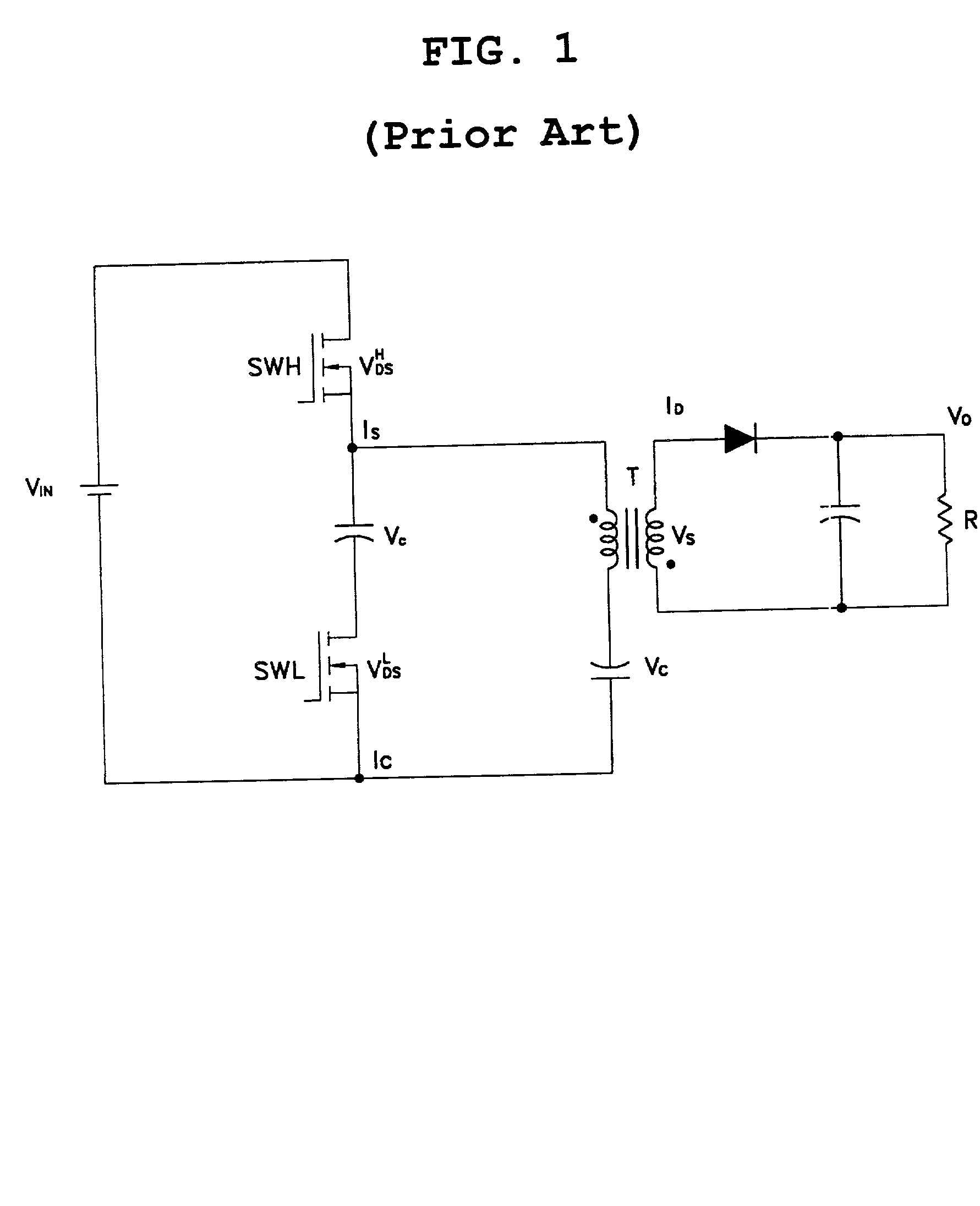
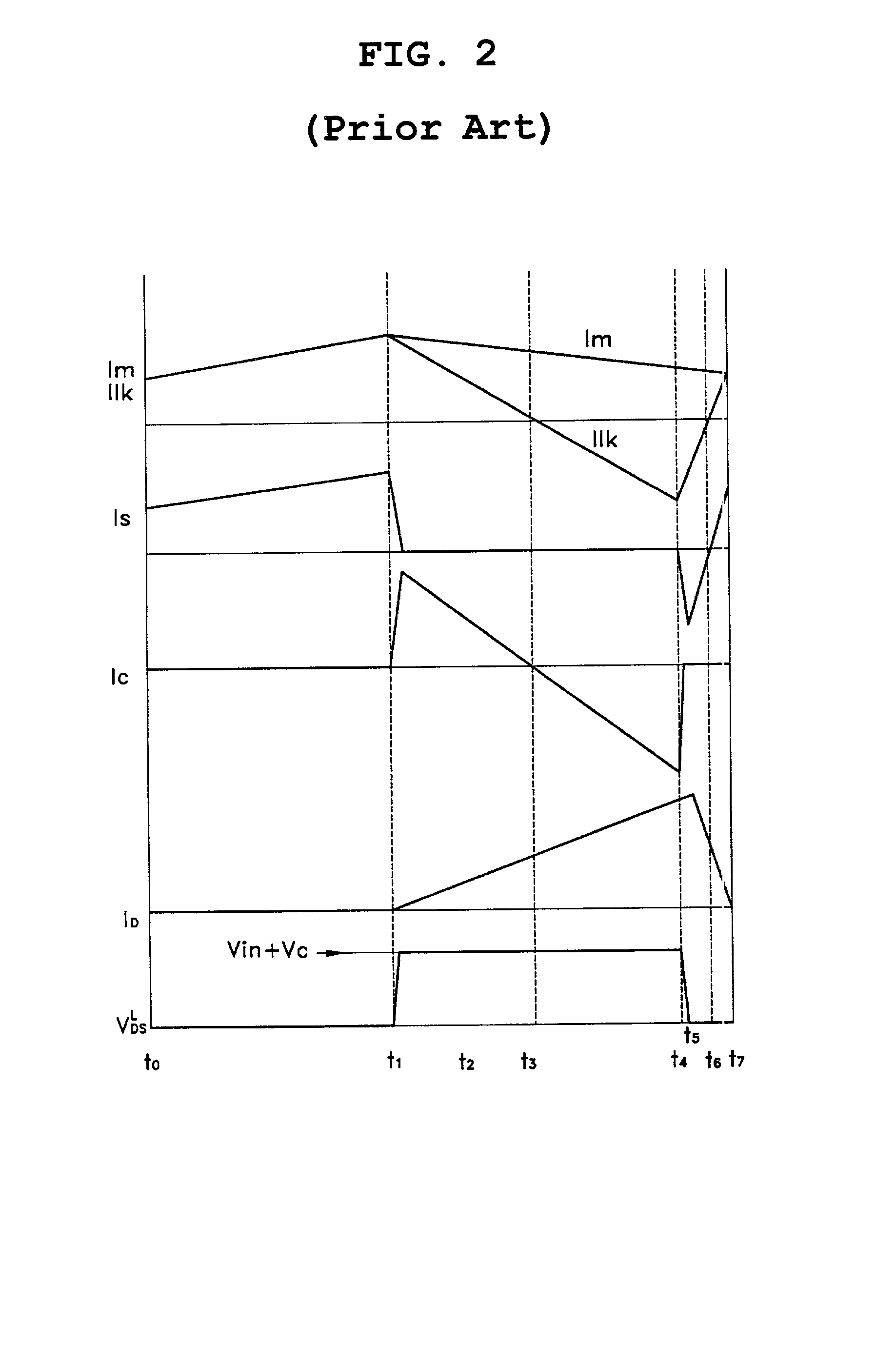
[0031] FIG. 5 is circuit diagram that shows converter configuration according to the present invention and FIG. 6 is wave shape diagram that shows action by FIG. 5.

[0032] Referring to FIG. 5, it comprises in same manner as in FIG. 1 high side switch SWH and low side switch SWL making a closed circuit with input voltage Vin and each making a switching action that is opposite to each other according to output signal of external driver (not shown in Figure), first capacitor C1 connected in series between the above SWH and SWL, a diode D connected to the above C1 in parallel, a transformer T that induces prim...


PUM


Abstract

A high efficiency converter for ZVS {zero voltage switching} is disclosed above which can reduce drain-source voltage of switch (MOSFET), heighten adapter efficiency and eliminate need of input voltage doubler circuit by means of making the converter to act in ZVS for wide range of whole input voltage where the converter is particularly featured by comprising high side switch (SWH) and low side switch (SWL) making a closed circuit with input voltage and each making a switching action that is opposite to each other according to output signal of external driver, first capacitor connected in series between the above SWH and SWL, a transformer that induces primary side voltage to secondary side according to switching action of the above SWH and SHL, and a rectifier that rectifies output voltage of secondary side of the above transformer while moreover the converter comprises a diode connected to the above first capacitor in parallel, first and second feedback diodes respectively connected to the above SWH and SWL in parallel, and second capacitor connected to primary coil of the above transformer in series.

Description

BACKGROUND OF THE INVENTION[0001] 1. Field of the Invention[0002] This invention relates a high efficiency converter for ZVS {zero voltage switching}, particularly that having both advantages of traditional active clamp flyback circuit and asymmetric flyback circuit so as to act in ZVS for whole wide range of input voltage.[0003] 2. Description of the Prior Art[0004] Recently we are under state of continual inevitable request of system specification augmentation such as multimedia system construction, acceleration of CPU to high speed, memory increase according to worldwide trend that notebook PC becomes day by day smaller, lighter, slimmer and pursuing high functionalization.[0005] And as capacity for each resource of each system specification is increasing, though now AC adapter for notebook PC uses 45.about.50 watts, gradually need is rising up for making high capacity of 60 W, 75 W, 80 W or more, for making it a micro slip easy and simple of carrying and handling, and for high e...

Claims


Application Information

Patent Timeline
IPC IPC(8): H02M3/28H02M3/335H02M3/337
CPCH02M3/337H02M3/33571H02M7/12
Inventor LEE, SANG YUN
Owner SAMSUNG ELECTRO MECHANICS CO LTD
Why Eureka
Try Eureka