
Apparatus having partially gold-plated surface

Inactive Publication Date: 2001-09-13
AMERSHAM HEALTH
View PDF0 Cites 24 Cited by
  • Summary
  • Abstract
  • Description
  • Claims
  • Application Information

AI Technical Summary

Benefits of technology

[0006] We have found that a change in surface properties of the apparatus surfaces results from steam sterilization and that this may be reduced or avoided by the use of apparatus with more hydrophilic post-sterilisation surfaces, e.g. gold surfaces.
[0007] Thus, one aspect the invention provides a process for the preparation of a mixture comprising a discontinuous phase in a continuous phase which comprises using a mixing apparatus having a non-porous mixing surface which is repellant to the discontinuous phase and / or attractive to the continuous phase when the continuous phase is liquid or which is attractive to the discontinuous phase when the continuous phase is gaseous, whereby to improve the efficacy of the preparation of said mixture and / or to reduce physical degradation of said mixing surface, said surface if hydrophilic being more hydrophilic after sterilisation than is stainless steel and if hydrophobic being more hydrophobic after sterilisation than is stainless steel.
[0014] In one embodiment, the mixing surface may form part of a mixing apparatus such as an extruder as described in more detail below. Such extruders are especially suitable for the production of emulsions and work advantageously when some of the surfaces of the extruder which contact the reaction mixture are coated with gold. Such extruders may also reduce problems associated with filter clogging. Desirably however such surfaces are ones over which the materials being mixed flow at a rate which is higher than that at which they flow over other surfaces in the mixing apparatus.

Problems solved by technology

We have now found however that mixing apparatus made of stainless steel and subjected in use to high shear forces may suffer a reduction in efficacy following steam sterilization.

Method used


Image

  • Apparatus having partially gold-plated surface
  • Apparatus having partially gold-plated surface
  • Apparatus having partially gold-plated surface

Examples


example 1

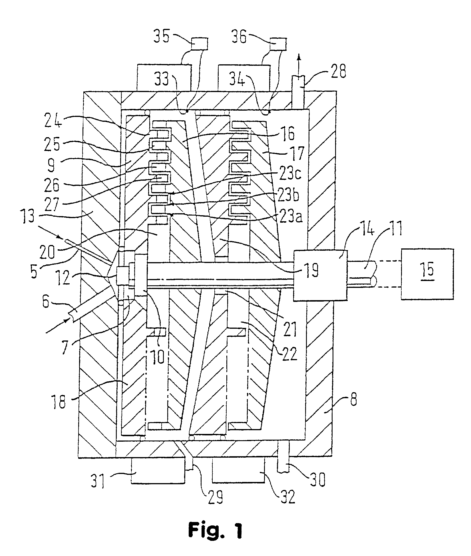
[0034] Referring to FIG. 1, there is shown a rotor: stator mixer. Gas (e.g. a perfluorocarbon such as perfluorobutane) and liquid (e.g. an aqueous phospholipid mixture) are introduced through inlets 5 and 6 respectively into premixing chamber 7, the walls of which are defined by a concave section of housing 8, first stator element 9, and the tip 10 of rotor drive shaft 11.

[0035] Tip 10 of rotor drive shaft 11 carries a flange 12 (seen side-on) which serves to mix gas and liquid in pre-mix chamber 7.

[0036] Housing 8 provides a cylindrical chamber and has a cup-shaped portion 8 and an end cap 13 with rotor drive shaft 11 entering through the base of portion 8 and sealed by a double mechanical seal 14. Drive shaft 11 is rotated for example at speeds of up to 8000 rpm by externally positioned motor 15 and rotates first rotor 16 and second rotor 17 which are in interlocking engagement with first stator 18 and second stator 19. The rotors and stators are gold plated to a thickness of 2 to...

example 2

[0042] In a typical example of the use of the mixer apparatus of Example 1, drive shaft 11 is rotated at 8000 rpm or such a rate as to cause outer shear force zone 23 to have a relative rotor:stator speed of at least 32 m / s, e.g. 46 m / s.

[0043] Gold plated rotor:stator assemblies are novel and form a further aspect of the invention.

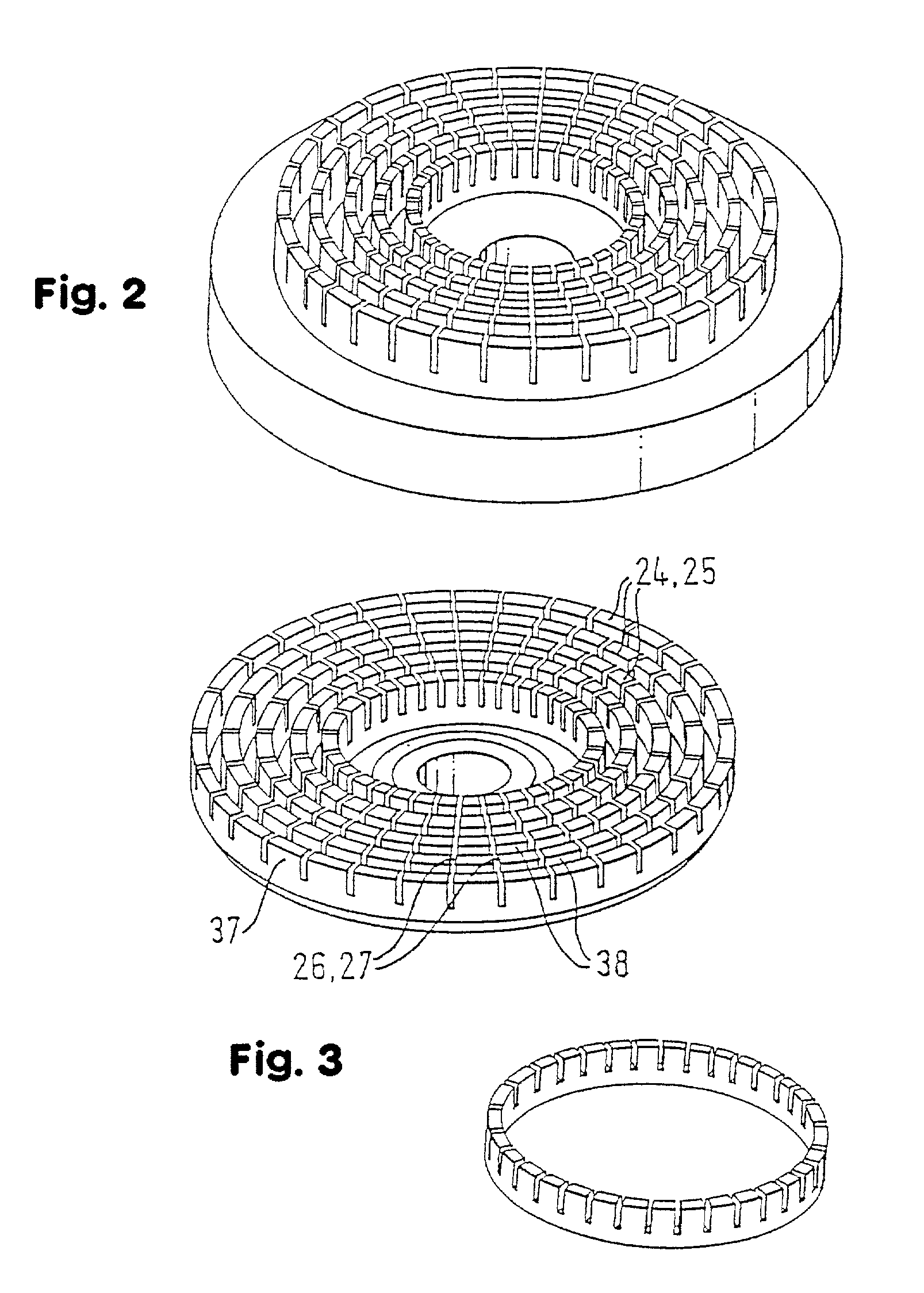
[0044] Referring to FIG. 2, it may be seen that the cylindrical extensions (flanges) 24,25 and axial slots 26,27 of the stators and rotors are axially extending and comprise a plurality of axially extending "teeth" 37 separated by a corresponding plurality of circumferentially evenly spaced, axially and radially extending apertures 38. In use, the materials being mixed pass through these apertures into successive shear force application zones defined by the circumferential sides of adjacent cylindrical extensions and axial slots.

[0045] Referring to FIG. 3, there is shown a representation of an individual flange 24,25.

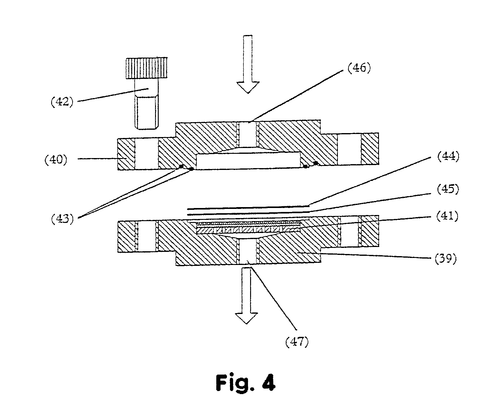
[0046] Referring to FIG. 4, there is sh...

example 3

[0047] Rotor:stator assemblies as described, made of stainless steel 316 L or gold plated stainless steel 316 L were tested for yield (million / mL as determined using a Coulter Multisizer) of 3-5 .mu.m microbubbles and for surface hydrophilicity (receding contact angle at 25 EC). The assemblies were untreated (U), steam sterilized for 1 hour (1S), unplated (316), gold plated (G), roughened (E), and / or steam sterilized for 15 production / sterilization cycles, each involving 1 hour of steam sterilization (15S). The yields and contact angles are set out below:

1 Surface Yield (million / mL) Contact angle (E) 316.U 1200-2000 13 316.1S 500 60 316.1SE 500 70 G.U 1400 18 G.1S 1200 26 G.15S 1000 43

[0048] As can be seen, the gold plated assemblies did not suffer the rapid drop off in yield subsequent to sterilization associated with the unplated assemblies.


PUM

PropertyMeasurementUnit
Sizeaaaaaaaaaa
Sizeaaaaaaaaaa
Lengthaaaaaaaaaa

Abstract

A change in the surface properties of apparatus for pharmaceutical preparation results from steam sterilization. This change may be avoided by the use of apparatus with more hydrophilic post-sterilization surfaces, e.g. those of gold. Hence there is provided a process for the preparation of a mixture comprising a discontinuous phase in a continuous phase which comprises using a mixing apparatus having a non-porous mixing surface which is repellant to the discontinuous phase and / or attractive to the continuous phase when the continuous phase is liquid or which is attractive to the discontinuous phase when the continuous phase is gaseous, whereby to improve the efficacy of the preparation of said mixture and / or to reduce physical degradation of said mixing surface, said surface if hydrophilic being more hydrophilic after sterilization than is stainless steel and if hydrophobic being more hydrophobic after sterilization than is stainless steel.

Description

[0001] This is a continuation of International Application PCT / GB99 / 02741, with an international filing date of Aug. 18, 1999.BACKGROUND OF INVENTION[0002] This invention relates to improvements in and relating to apparatus used for production of a pharmaceutical product comprising a continuous aqueous phase containing a discontinuous water-immiscible phase, in particular high shear mixer apparatus.[0003] In the preparation of pharmaceuticals, it is important that the apparatus used should be capable of sterilization. This is generally achieved for large scale apparatus by steam sterilization, i.e. by passing steam, usually superheated steam, through the apparatus between production runs.[0004] Much of the large scale apparatus used in pharmaceutical production is made of stainless steel because of its chemical inertness, corrosion resistance, ease of production and simplicity of sterilization.[0005] We have now found however that mixing apparatus made of stainless steel and subject...

Claims


Application Information

Patent Timeline
IPC IPC(8): B01F3/04B01F5/00B01F7/00B01F13/10
CPCB01F3/04007B01F3/04099B01F7/00041B01F7/00633B01F7/00766B01F13/1013B01F13/1016B01F2005/0008B01F2013/1052B01F2215/0032B01F23/21B01F23/23B01F2025/912B01F27/0531B01F27/2711B01F27/191B01F33/811B01F33/81B01F33/834B01F2101/22
Inventor OMTVEIT, TOREHONERUD, ANN-KRISTIN
Owner AMERSHAM HEALTH
Learn More