
Method and system for transaction of electronic money with a mobile communication unit as an electronic wallet

a mobile communication unit and electronic wallet technology, applied in the field of electronic money system, can solve the problems of users' dislike of using credit cards, conventional credit card systems are not suitable for electronic commerce applications, and conventional credit card systems are not suitable for kids to us

Inactive Publication Date: 2001-07-12
INFOHUB
View PDF3 Cites 247 Cited by
  • Summary
  • Abstract
  • Description
  • Claims
  • Application Information

AI Technical Summary

Benefits of technology

[0014] It is further an object of the present invention to provide an electronic wallet and operating method wherein even small-size electronic commerce can be safely and conveniently performed.
[0016] It is another object of the present invention to provide an electronic monetary system and method that allows the user to perform all kinds of electronic transactions on internet and / or wireless network.
[0021] As a result, it becomes possible to implement a secure and convenient monetary system for electronic commerce and transactions on internet.

Problems solved by technology

However, since the disclosure of the credit card number and the user's information during the purchasing step is vulnerable to the attack from a hacker, the conventional credit card system is not adequate for an electronic commerce application.
Furthermore, since the youngsters under eighteen years of age are not allowed to be issued a credit card, the conventional credit card system is not appropriate for the kids to use for paying for the small items such as MP3 music file.
Furthermore, there is a tendency that the internet users dislike to use the credit card as a payment means especially for a small-size purchasing item because of the possibility of hacking problem.
Moreover, it is inconvenient because the customer does not have an alternative way to check his balance of account other than the card reader.
The conventional card system still lacks the security means against the hacker's attack.
However, the encrypted number system of the prior art still suffers from the shortcoming in that the user has to memorize a long number of 12.sup..about.16 digits.
Further, it is still difficult to tell the differences between the genuine user and the fake for a specific encrypted number under processing.

Method used


Image

  • Method and system for transaction of electronic money with a mobile communication unit as an electronic wallet
  • Method and system for transaction of electronic money with a mobile communication unit as an electronic wallet
  • Method and system for transaction of electronic money with a mobile communication unit as an electronic wallet

Examples


first embodiment

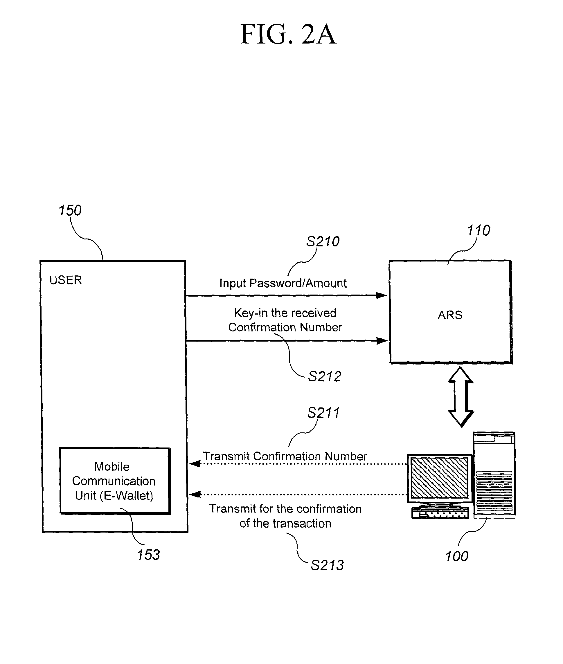
[0042] FIG. 2A is a schematic diagram illustrating the workflow of opening a new electronic account in accordance with the present invention.

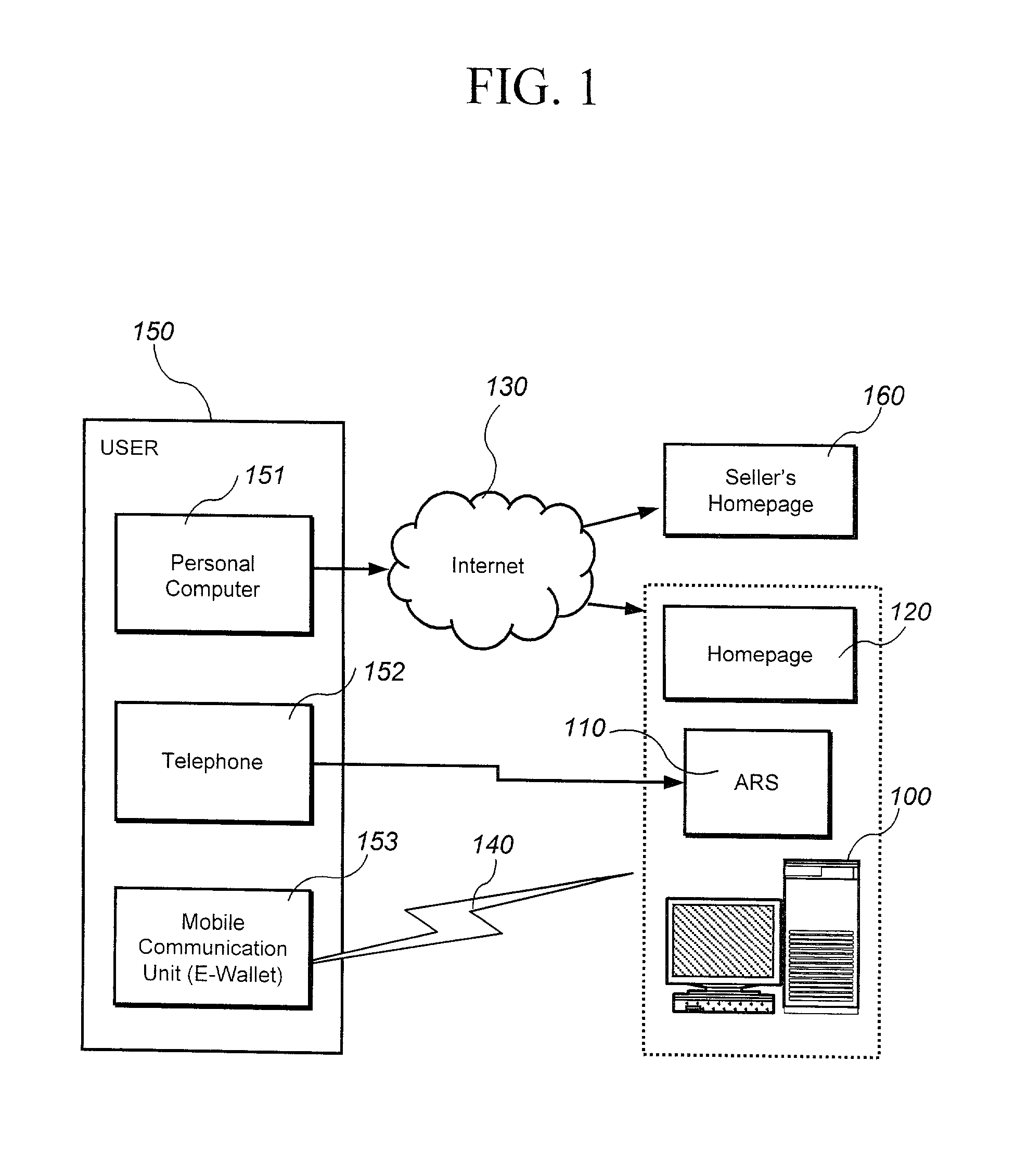
[0043] Referring to FIG. 2A, the user 150 makes a phone call to the ARS server 110 of the E-wallet managing company and keys in his phone number of the mobile communication unit 153, his password, and the amount of money to be initially deposited in his new account (step S210).

[0044] The ARS server 110 then sends a stream of a randomly generated confirmation number to the user's mobile communication unit (E-wallet; 153) through a wireless network (step S211). The confirmation number sent from the ARS server 110 is then displayed on the LCD monitor of the user's E-wallet 153.

[0045] After reading the confirmation number displayed on the display of his mobile communication unit, the user 150 enters the confirmation number by using the buttons on the keypad of his mobile communication unit in order to send back the confirmation number. The successf...

second embodiment

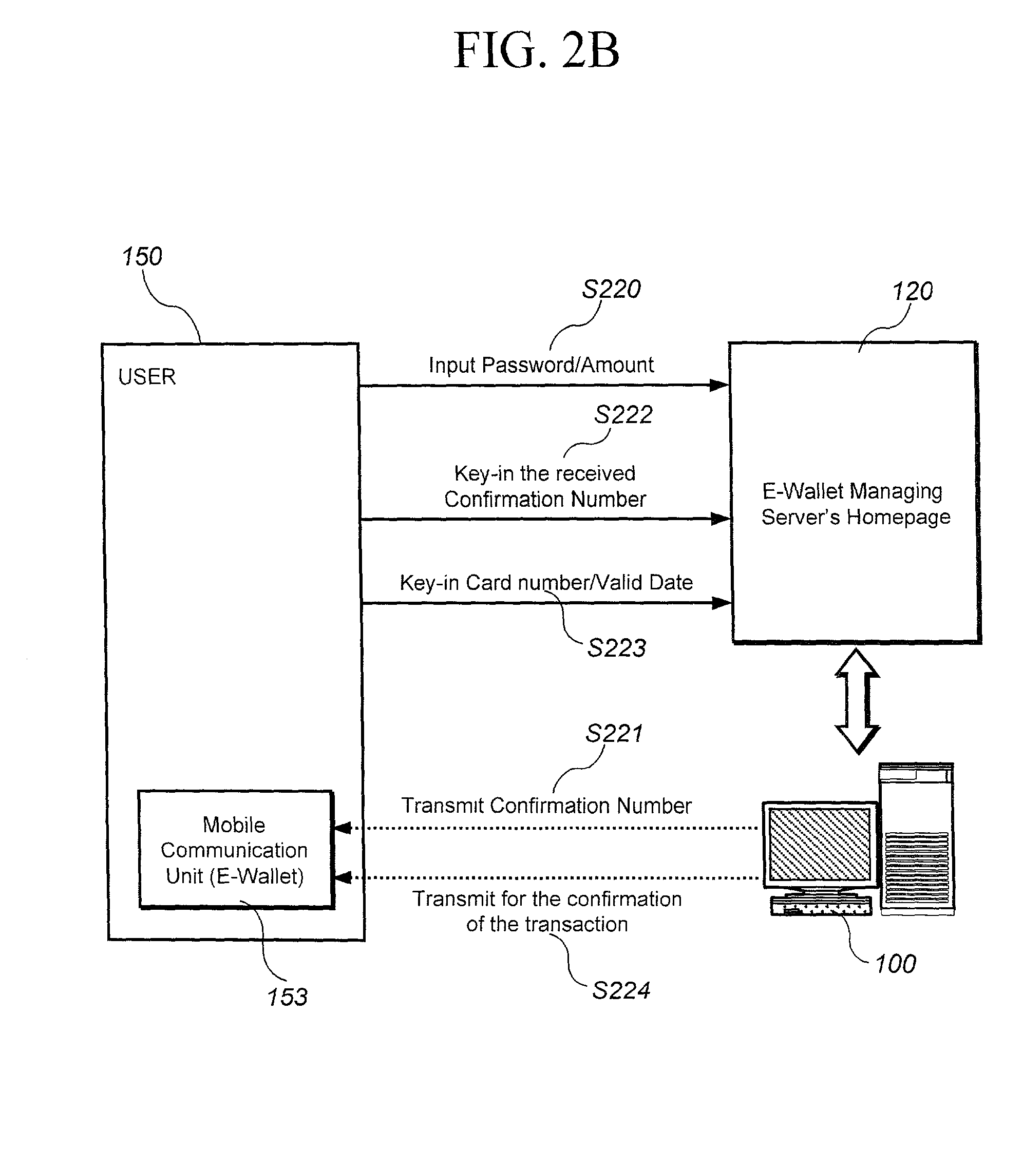
[0051] FIG. 2b is a schematic diagram illustrating the workflow of opening a new electronic account in accordance with the present invention.

[0052] Referring to FIG. 2b, the user 150 can visit the homepage 120 of the E-wallet managing server 100 in accordance with the present invention and request to open a new electronic account on internet.

[0053] The user can enter the information about the phone number of his mobile communication unit (i.e. E-wallet) 153, his password, and the requested amount of money for his new electronic account (step S220) on internet.

[0054] The E-wallet managing server 100 transmits a confirmation number (step S221) to the mobile communication unit (or an E-wallet) identified by the phone number that the user entered at a step of S220.

[0055] The user 150 now reads the confirmation number displayed on the screen of his E-wallet 153 and enters the received confirmation number in the appropriate box provided on the E-wallet managing server's homepage 120 (step...

third embodiment

[0060] FIG. 2c is a schematic diagram illustrating the workflow of opening a new electronic monetary account in accordance with the present invention.

[0061] Referring to FIG. 2c, the user 150 can open a new electronic account by transferring money from a bank account. Namely, the user 150 can provide information about the name of the sender, date of transfer, and the amount of transfer in the web page 120 of the E-wallet managing server 100 (step S 230) after sending the money to an account of the company of the E-wallet managing server.

[0062] The E-wallet managing server 100 confirms the transfer of money for opening a new electronic account (step S231). Then the user 150 enters the phone number of his mobile communication unit (E-wallet) and password in the appropriate box provided by the homepage 120 of the E-wallet managing server 100 (step S232).

[0063] Thereafter, the confirmation process in accordance with the present invention is followed. Namely, a randomly generated confirm...


PUM


Abstract

A electronic monetary system comprising a mobile communication unit as an electronic wallet for transactions including electronic payments, money transfer, and recharging the electronic account. The security of the electronic transactions is confirmed by circulating a confirmation number through a loop formed by an E-wallet managing server through the wireless network to the mobile communication unit of the user.

Description

[0001] The present invention relates to an electronic monetary system, and particularly to an electronic money transfer system including electronic wallet for secure electronic transactions and an operating method thereof.DESCRIPTION OF THE RELATED ART[0002] The present invention relates to an electronic money system for implementing electronic money payment system as an alternative means to the conventional payment medium such as cash, checks, credit and debit cards.[0003] The conventional credit card allows the internet user to make a purchase from a vendor simply by recording the credit card number and validation date on the cyber voucher displayed on the user's computer screen on the network.[0004] However, since the disclosure of the credit card number and the user's information during the purchasing step is vulnerable to the attack from a hacker, the conventional credit card system is not adequate for an electronic commerce application.[0005] Furthermore, since the youngsters ...

Claims


Application Information

Patent Timeline
IPC IPC(8): G06Q20/04G06Q20/10G06Q20/22G06Q20/28G06Q20/32G06Q20/36G06Q20/38G07F7/08
CPCG06Q20/04G06Q20/10G06Q20/223G06Q20/28G06Q20/32G06Q20/3223G06Q20/3226G06Q20/325G06Q20/3255G06Q20/363G06Q20/3678G06Q20/382G07F7/0866
Inventor LEE, JONG-II
Owner INFOHUB
Learn More