Data centre

a data center and electrical equipment technology, applied in data processing centers, cooling/ventilation/heating modifications, support structure mounting, etc., can solve problems such as reducing maintenance requirements

Active Publication Date: 2022-08-16
BRIPCO UK
View PDF4 Cites 0 Cited by
  • Summary
  • Abstract
  • Description
  • Claims
  • Application Information

AI Technical Summary

Benefits of technology

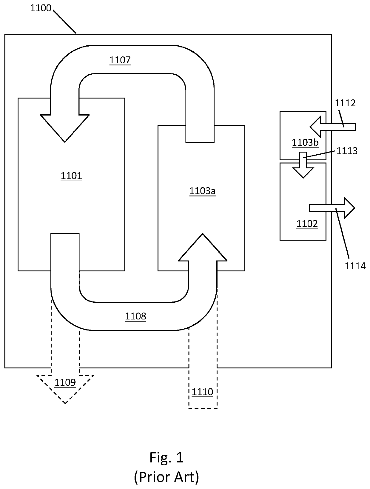
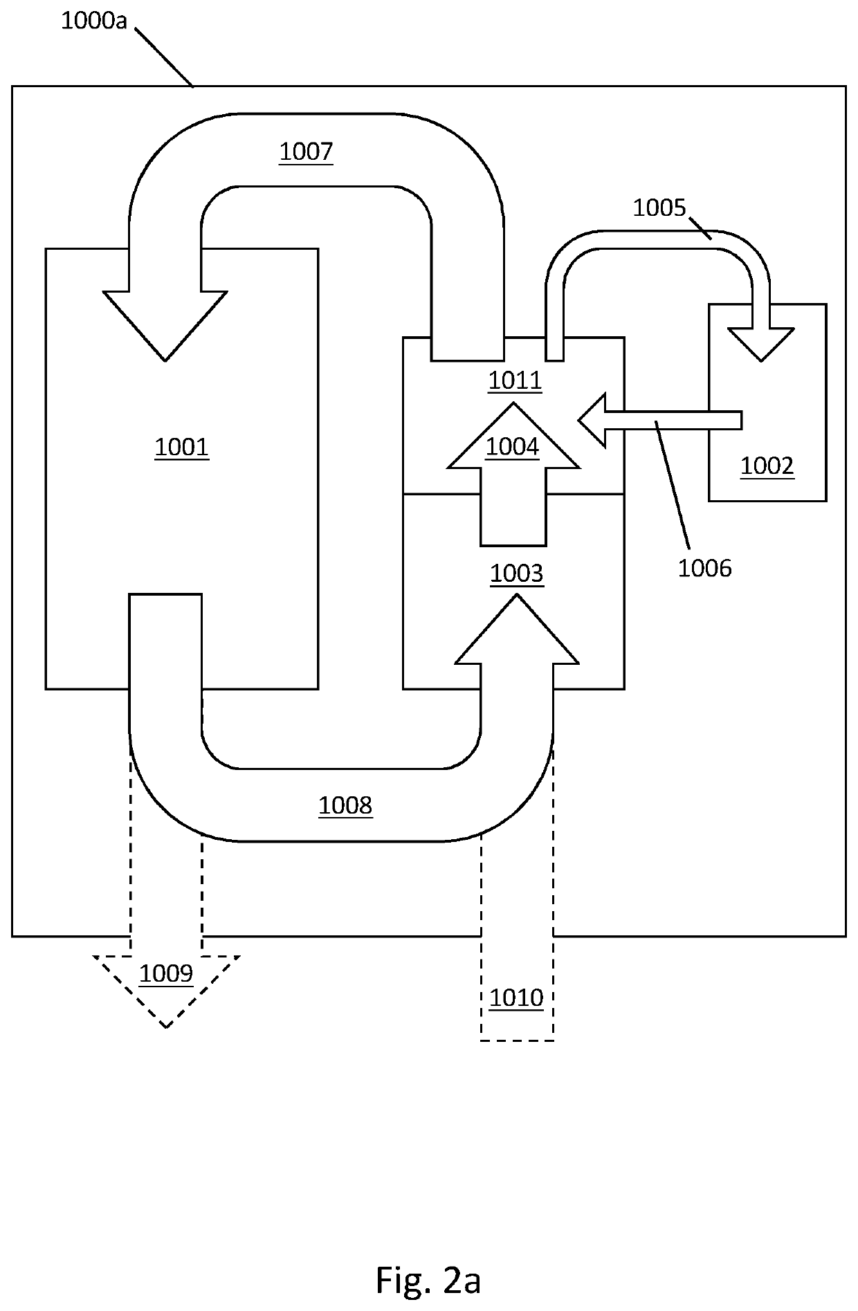
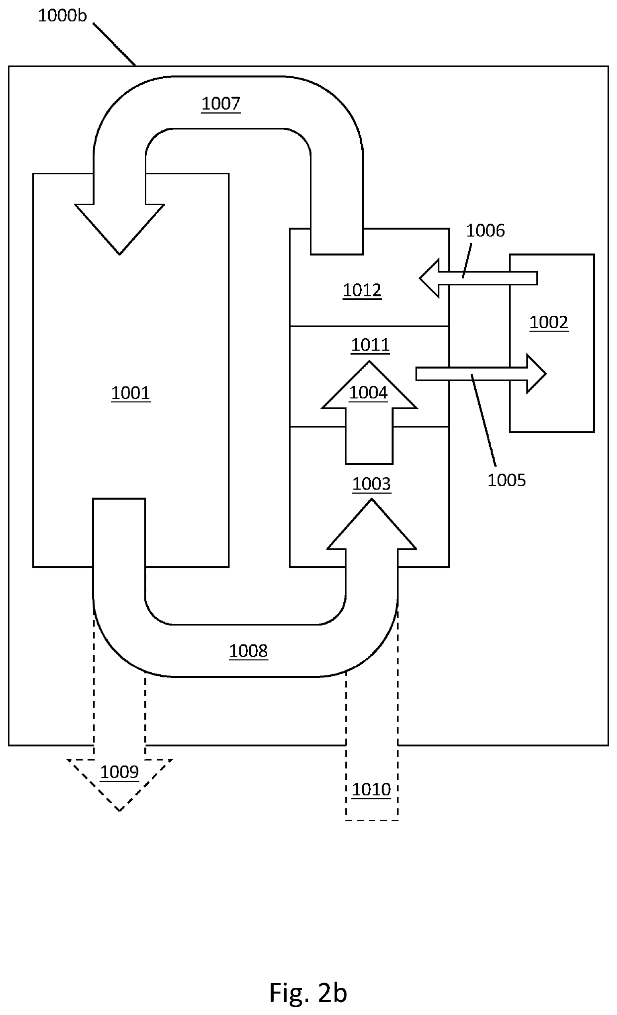
[0016]Dividing the services area into a hot zone and a cold zone may improve cooling efficiency in the services area, for example because cooling air is supplied directly to the items of equipment to be cooled without mixing with warm air already used for cooling. Supplying the services area with cooling air from the air handling unit used to provide cooling air to IT equipment in the data centre may improve cooling efficiency because the large scale of the air handling unit. Furthermore, it may reduce maintenance requirements as compared to a data centre having a dedicated cooling system for its services area.
[0028]It is often the case that the cooling capacity of an air handling unit is limited by the flow rate of cooling air that it is capable of supplying. It has been found that individual server fans are typically configured by the server manufacturer to operate at a set speed, irrespective of the temperature of server components (i.e. the server will draw the same volume of cooling air, regardless of the temperature of the cooling air). Thus, to provide adequate cooling capacity, the air handling unit should be able to supply x m3 / s of cooling air to the cold aisles (where x represents the total cooling airflow required by all servers in the data centre when all racks located along all cold aisles supplied by the air handling unit are full). When warm air from the services area is returned to the cooling airflow path between the air handling unit and the cold aisles, the air handling unit still needs to be capable of providing x m3 / s of cooling air. If warm air is not so returned, the air handling unit may need to be capable of supplying x+y m3 / s of cooling air (x as previously defined, y represents the total cooling airflow required by services area). It is often the case that cooling equipment in an air handling unit has a maximum threshold for air velocity, for example 5 m / s. Thus, it may be necessary to provide a larger air handler having an increased amount of equipment to supply x+y m3 / s of cooling air. It will be appreciated that the services area may be able to be cooled using the IT equipment air handling unit without increasing the cooling capacity of the air handling unit when the services area is configured to return warm air to the cooling airflow path. Thus, with such an arrangement, the data centre operator can make use of the large scale efficiencies provided by the said air handling unit without increasing the capacity of said air handling unit.
[0041]Preferably, the data centre is configured so that, in use, electrical power from an external power distribution network is supplied to electrical equipment in the data centre via an electrical switchboard and via a UPS switchboard, for example wherein electrical power from the external power source first passes through an electrical switchboard, then through a UPS switchboard, then back through the electrical switchboard and finally to the electrical equipment. Electrical equipment may include e.g. IT equipment mounted in racks in the rack storage areas and / or mechanical equipment such as the air handling unit. Preferably, the UPS switchboard is operable in a plurality of modes including, for example, (i) bypass mode in which electrical power supplied to the rack storage areas bypasses the UPS power source, (ii) eco mode in which a portion of electrical power passes through the UPS power source (thus allowing trickle charging of the UPS power source), (iii) double conversion mode in which all power passes through the UPS power source, and (iv) discharge mode in which all power is supplied by the UPS power source. It will be appreciated that in modes (i) to (iii), power is supplied by an external power source. Modes (i) to (iii) provide a balance between UPS responsiveness, power efficiency and heat generation. In bypass mode, the UPS system provides its maximum efficiency (since no power is lost by passage through the UPS power source), least responsiveness (since the UPS switchboard has to connect the UPS power source to the electrical circuit and begin converting between DC and AC, e.g. when batteries are the UPS power source), and least heat generation (since the UPS switchboard is not converting electrical current from AC to DC and back to AC). In double conversion mode, the UPS system provides its minimum efficiency (since all power is passed through the UPS power source), maximum responsiveness (since the UPS power source is able to instantaneously step in to supply power if there is a loss of power from the external power source), and most heat generation (since all electrical current in the circuit is being converted from AC to DC and back to AC). In practice, bypass mode is likely only to be used during maintenance of the UPS system, and discharge mode is only used upon failure of the external power supply. Risk averse data centre operators may continuously operate UPS systems in double discharge mode, while others may prefer the efficiency gain of operating in eco mode.
[0059]Optionally, the method comprises mixing the third warm air stream with cool air in the cooling air plenum, for example by directing the third warm air stream into the cooling air plenum. It may be that in such an arrangement the third warm air stream is mixed with the first cool air stream, for example such that the second cool air stream and the fourth mixed air stream have substantially the same composition. It may be that when the airflow mixing point is upstream of the airflow splitting point, mixing of air in the fourth mixed air stream can be conveniently improved. It will be appreciated that in such a configuration, the airflow rate in the portion of the airflow path between the airflow mixing point and the airflow splitting point is higher than in an arrangement where the airflow mixing point is downstream of the airflow splitting point. Thus, by inclusion of an air mixing device, such as air mixing baffles, between the airflow mixing point and the airflow splitting point, the relatively high velocity of airflow can assist in effectively mixing the air.

Problems solved by technology

Furthermore, it may reduce maintenance requirements as compared to a data centre having a dedicated cooling system for its services area.

Method used


Image

  • Data centre
  • Data centre
  • Data centre

Examples


Embodiment Construction

[0086]As used herein, the term ‘in use’ means during the normal use of the item so described. For example, a data centre is ‘in use’ when operating normally, for example when the items of IT equipment housed in the data centre are functioning, and the air handling unit is operating to provide adequate cooling air to the items of IT equipment. It will be appreciated that a data centre is operating normally whenever it is operating within its design thresholds. For example, when the data centre is operating at 20% of its maximum design capacity, or 100% of its maximum design capacity, it is operating normally.

[0087]A data centre is a facility for housing large numbers of densely packed computer servers. One approach classifying data centre size is by the total power consumption of the IT equipment in the data centre (when the data centre is at full IT equipment capacity). Small to medium-sized data centres may, for example, have a power consumption of 125 KW to 1.5 MW, large-scale dat...


PUM


Abstract

A data centre, a method of cooling electrical equipment in a data centre, and a services module for a data centre, are disclosed. The data centre is for accommodating a plurality of racks of IT equipment and comprises: a) a plurality of hot aisles interleaved with a plurality of cold aisles separated by IT equipment rack storage areas; b) an air handling unit configured to supply cooling air to the cold aisles; c) a services area for accommodating at least one UPS switchboard for directing electrical power to a plurality of IT equipment racks, the services area comprising hot and cold zones, a hot zone being separated from a cold zone by at least one of (i) a UPS switchboard storage area and (ii) a partition; wherein, in use, cooling air is supplied to the UPS switchboard storage area from the air handling unit via the cold zone of the services area.

Description

FIELD OF THE INVENTION[0001]The present invention concerns data centres and a method of cooling electrical equipment in a data centre. More particularly, this invention concerns data centre buildings having a services area for accommodating uninterruptible power supply (UPS) equipment, and methods of cooling said UPS equipment.BACKGROUND OF THE INVENTION[0002]A data centre is a late 20th Century development that has grown as a response to the increasing demand for computer processing capability and a recognition of the importance of IT in the place of every business and organisation today. With the ever-increasing demand for computing capacity in recent years, many large organisations have invested in data centres comprising many networked computer servers known as blades installed in racks enabling controlled and modular expansion of capacity. The racks also typically house telecommunications equipment such as routers to handle data flow between the computer servers and data flow b...

Claims


Application Information

Patent Timeline
Patent Type & Authority Patents(United States)
IPC IPC(8): H05K7/20
CPCH05K7/20745H05K7/20145H05K7/20836H05K7/1497E04H2005/005
Inventor THORNTON, WILLIAMFAVILL, AARON
Owner BRIPCO UK
Why Eureka
Try Eureka