
Microwave soil moisture sensor based on phase shift method and independent of electrical conductivity of the soil

a soil moisture sensor and phase shift technology, applied in the field of soil moisture sensor based microwaves, can solve the problems of virtually impossible to eliminate the influence of soil conductivity, substantial reduction of stated issue, and inability to accurately measure soil moisture content, etc., to achieve long-lasting operation, reduce the need for calibration, and more immune to noise

Active Publication Date: 2022-08-09
BIOSENSE INST RES & DEV INST FOR INFORMATION TECH IN BIOSYST
View PDF9 Cites 0 Cited by
  • Summary
  • Abstract
  • Description
  • Claims
  • Application Information

AI Technical Summary

Benefits of technology

The sensor provides long-lasting, accurate, and calibration-free measurements of soil moisture, capable of operating across a wide temperature range and varying soil types, suitable for IoT integration and agricultural applications.

Problems solved by technology

The main disadvantage of this type of sensors is the fact that conductivity of the soil is not exclusively related to the soil moisture, but also to the concentration of the ions in the soil.
Therefore, it is practically impossible to eliminate this influence.
The stated issue is substantially diminished when gypsum block sensors are used, since they saturate water from the soil by ions and in this way cancel the influence of the soil conductivity.
However, resolving the problem of variable soil conductivity has generated another issue, since the gypsum block dissolves over time and the contact with surrounding soil is lost, which ultimately lowers the quality of measurements.
Moreover, the measurement method is limited in terms of electrical conductivity to values higher than 6 dS / m.
Although the stated approach has eliminated the issue of the poor contact between the sensor and soil, the other disadvantages of the previous solution remained—including depletion of gypsum tablet, long response time, temperature dependence, and inapplicability of the sensor in swelling soil.
This change influences the propagation velocity of electromagnetic wave in the dielectric and therefore the time delay of the signal.
The precision of the reflectometric methods is limited by multiple reflection phenomena caused by soil inhomogeneity.
However, sensors based on transmission method require two ports, which creates additional challenges in sensor design in a way that both ports are placed in the soil.
The main disadvantage of impedance sensors is the requirement for expensive equipment such as VNA or impedance analyzer, which limits their use to laboratory conditions.
However, the proposed sensor is dependent on the type of the soil and demands calibration before usage since the frequency is relatively low.
However, this type of sensor has disadvantage caused by the formation of gaps between porous medium and surrounding soil that dries, which enables entering of air into the porous material, therefore dynamic range of the tensiometer is from 0 to −85 kPa.
Hence, tensiometers are not suitable for the swelling soil.

Method used


Image

  • Microwave soil moisture sensor based on phase shift method and independent of electrical conductivity of the soil
  • Microwave soil moisture sensor based on phase shift method and independent of electrical conductivity of the soil
  • Microwave soil moisture sensor based on phase shift method and independent of electrical conductivity of the soil

Examples


Embodiment Construction

[0028]Before disclosing the details of the invention, it is important to understand and stress that the present invention is not limited to the details of the construction illustrated and described below. The terms used in the description of the invention serve to understand the invention, and not for its limitations.

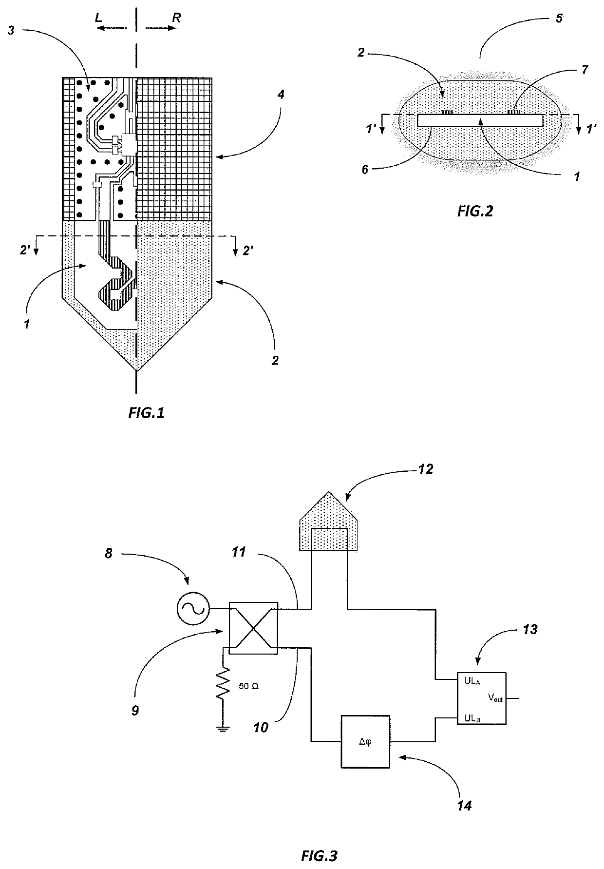
[0029]An example of the realization of the soil moisture sensor is shown in FIG. 1. The side marked with L is the cross-section of the sensor defined in FIG. 2 by 1′-1′, while side R is the exterior of the sensor. The basic components of the sensor are the sensor element 1, which is in direct contact with the porous matrix 2, phase shift measurement circuit 3, and the protective layer of the electronic circuit 4. The operating principle of the sensor and its components will be described in detail below.

[0030]The operating principle of the sensor is based on the phase shift method. The advantage of this method lays in the fact that phase measurement is less susceptible t...


PUM

PropertyMeasurementUnit
electrical conductivityaaaaaaaaaa
relative permittivityaaaaaaaaaa
frequencyaaaaaaaaaa

Abstract

The present invention relates to soil moisture and soil matric potential measurement using microwave sensor composed of sensor element (1), porous matrix (2), phase shift measurement circuit (3) and circuit protective layer (4). Operating principle is based on the phase shift method in which phase shift of the signal propagating along sensor element (1) is related to the porous matrix (2) moisture content. Porous matrix (2) is in contact with surrounding soil (5) and reflects its water content. Phase shift measurement circuit (3) excite sensor element (1) and measures phase shift. The sensor is independent of soil electrical conductivity owing to the operating frequency in microwave range (˜GHz). In this manner, it is less sensitive to the soil type and therefore less demanding for calibration. The sensor is made of durable elements without consumable parts which enable a long-term operation. Its low power consumption makes it suitable for Internet of Things concept and automatic irrigation systems.

Description

TECHNICAL FIELD[0001]The present invention relates to sensors for determination of soil water content, and more particularly, to soil moisture determination by means of microwaves and changes in the dielectric constant of the material.BACKGROUND ART[0002]Exact measurement of soil moisture is needed in a variety of applications. In agriculture, proper growth, development, and maintenance of the plants significantly depend on soil water content. In the past, numerous sensors based on indirect methods for soil moisture measurement, were developed including electric conductivity method, dielectric permittivity method, tensiometric method and so on.[0003]An example of the sensor solution based on the measurement of electrical conductivity, are electric resistance sensors. Electrical conductivity of the soil is measured between the electrodes placed directly in the soil. Consequently, the resistivity of the medium, which is in direct contact with electrodes on one side and surrounding soi...

Claims


Application Information

Patent Timeline
Patent Type & Authority Patents(United States)
IPC IPC(8): G01N22/04G01N33/24
CPCG01N22/04G01N33/246
Inventor KITIC, GORAN
Owner BIOSENSE INST RES & DEV INST FOR INFORMATION TECH IN BIOSYST
Learn More