
Braking force control apparatus

Active Publication Date: 2022-08-02
TOYOTA JIDOSHA KK +1
View PDF7 Cites 0 Cited by
  • Summary
  • Abstract
  • Description
  • Claims
  • Application Information

AI Technical Summary

Benefits of technology

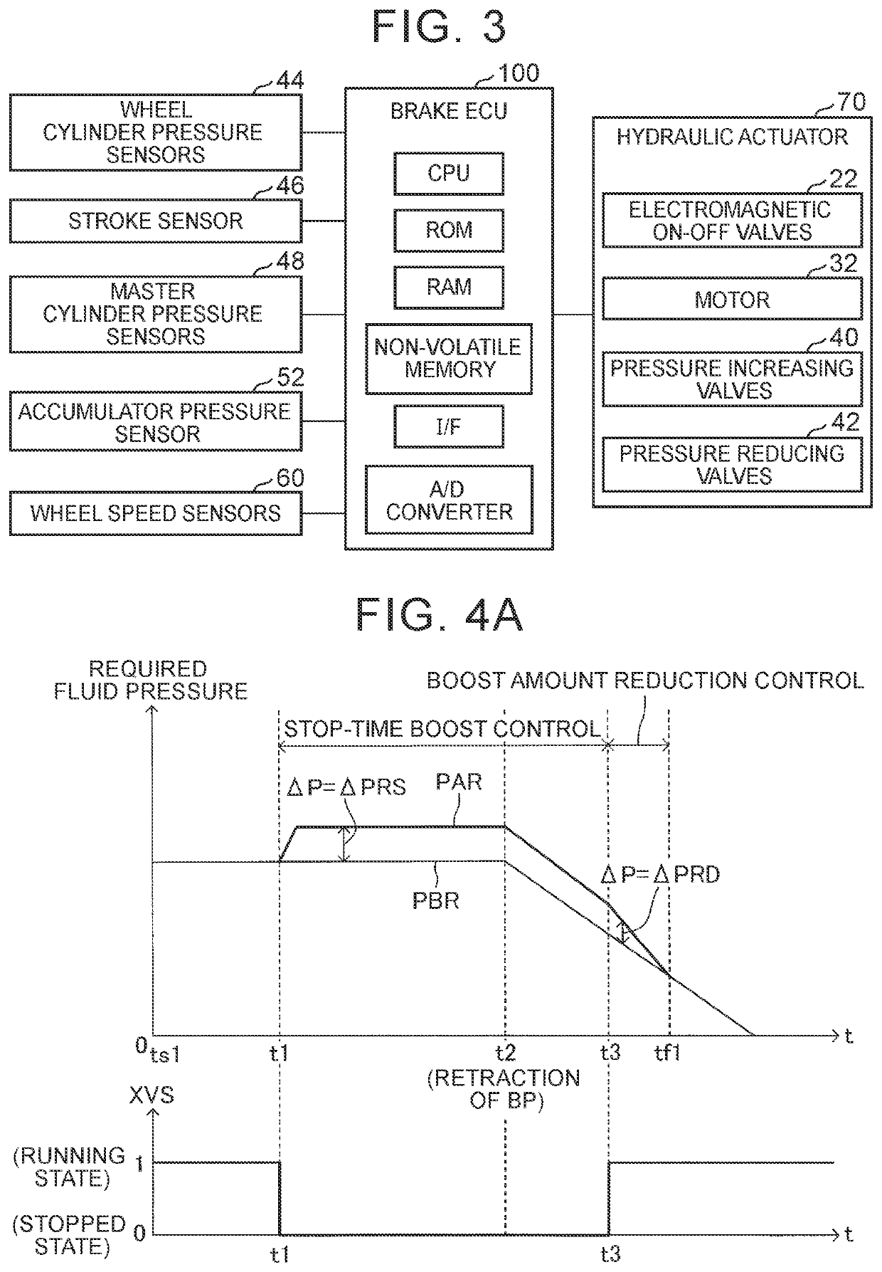
The patent describes a braking force control apparatus that reduces the possibility of a vehicle starting to move unintentionally as a result of heat reduction or depression force reduction. The apparatus performs stop-time boost control to boost the required fluid pressure when the vehicle state shifts from the running state to the stopped state. The boosted braking force prevents the braking force applied to each of the wheels from becoming smaller than the required braking force. The apparatus also performs boost amount reduction control to gradually decrease the boost amount with time to prevent the vehicle from starting to move quickly when it shifts from the running state to the stopped state again. Overall, the apparatus ensures safe and stable braking control during stopping and running of the vehicle.

Problems solved by technology

However, even when the required fluid pressure is constant, the pressing force decreases, so the braking force may decrease.
However, when a certain length of time elapses after the rotary member stops rotating, the volumes of both the members slightly decrease due to a fall in temperature.
As a result, a vehicle in a stopped state may start moving against a driver's intention.
In addition, when the vehicle is in the stopped state due to the driver's own operation of a brake pedal, the driver may unintentionally reduce the force (depression force) for performing depression operation of the brake pedal (hereinafter referred to also as “depression force reduction”).

Method used


Image

  • Braking force control apparatus
  • Braking force control apparatus
  • Braking force control apparatus

Examples


embodiments

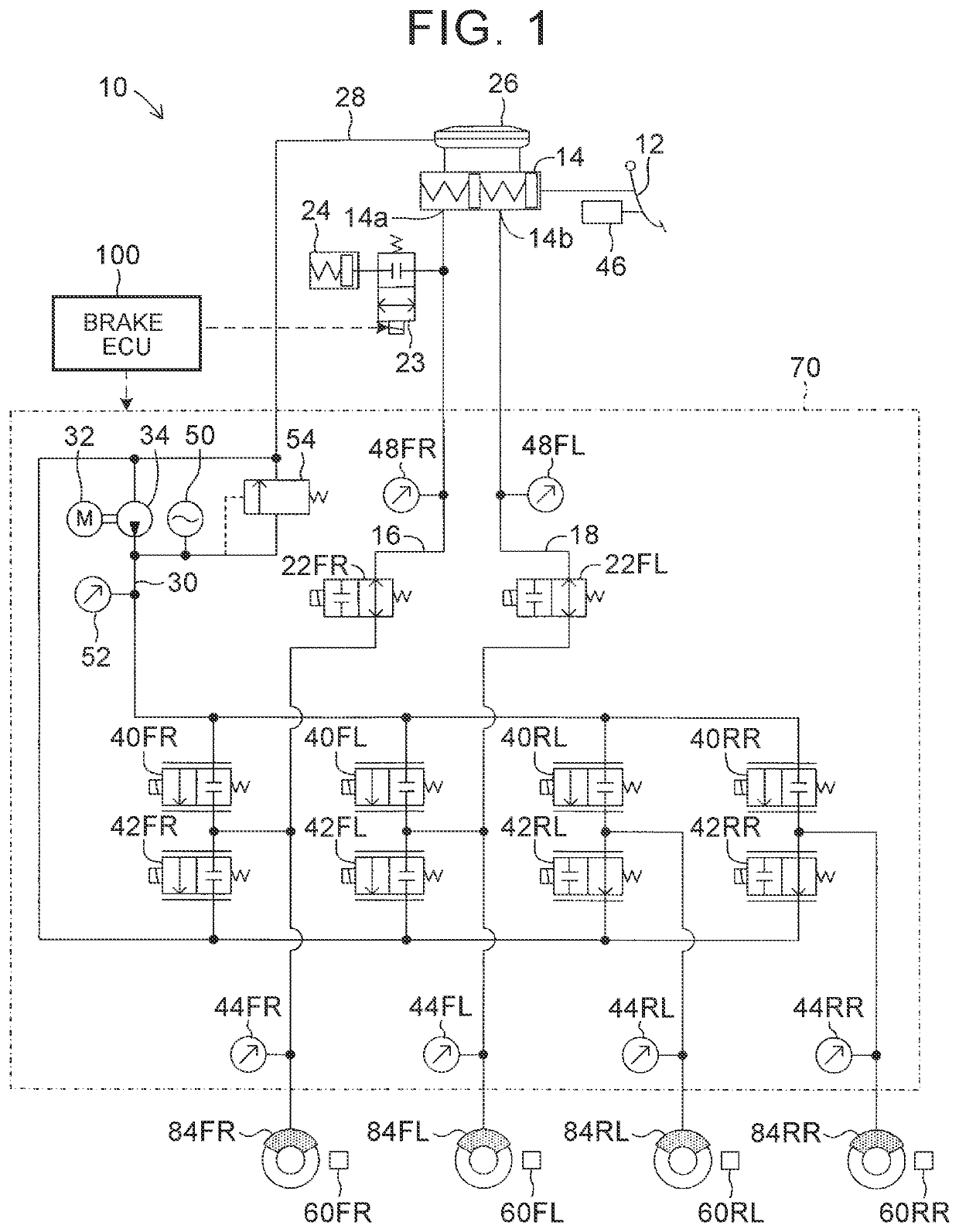
[0027]As shown in FIG. 1, a braking force control apparatus according to one of the embodiments of the disclosure (hereinafter referred to also as “the apparatus of the present embodiment) 10 constitutes a vehicular electronically controlled brake system (ECB), and controls braking forces that are applied to four wheels provided in a vehicle. The apparatus 10 of the present embodiment is mounted in, for example, a hybrid vehicle that is equipped with an electric motor and an internal combustion engine as drive sources for running. In this hybrid vehicle, regenerative braking for braking the vehicle through regeneration of kinetic energy of the vehicle into electric energy, and hydraulic braking by the apparatus 10 of the present embodiment can each be used to brake the vehicle. The vehicle that is mounted with the apparatus 10 according to the present embodiment can perform brake regeneration cooperative control for generating a desired braking force by combining this regenerative b...

modification example

[0096]A braking force control apparatus according to the modification example (which will be hereinafter referred to also as “the modified apparatus”, and a vehicle mounted with the modified apparatus will be hereinafter referred to also as “the own vehicle”) is different from the apparatus 10 of the present embodiment in that a brake ECU performs various kinds of driving support control, and that a braking request is created based on these kinds of driving support control. As driving support control, for example, adaptive cruise control (ACC), pre-crash brake control (PBC), and the like can be mentioned. The following description will focus on the difference from the apparatus 10 of the present embodiment.

[0097]ACC is well-known control for causing the own vehicle to run at a constant speed such that an actual vehicle speed thereof coincides with a set vehicle speed when there is no vehicle (preceding vehicle) running in front of the own vehicle, and causing the own vehicle to run ...


PUM


Abstract

A braking force control apparatus includes a fluid pressure generation mechanism, a braking mechanism and an electric control unit. The fluid pressure generation mechanism causes a braking mechanism to generate a required fluid pressure. The braking mechanism applies a braking force depending on the required fluid pressure to each of wheels through the pressing of a braking member against a rotating rotary member due to the required fluid pressure. The electronic control unit performs, when the required fluid pressure is generated and a vehicle state shifts from a running state to a stopped state at a first time point, stop-time boost control to boost the required fluid pressure at and after the first time point.

Description

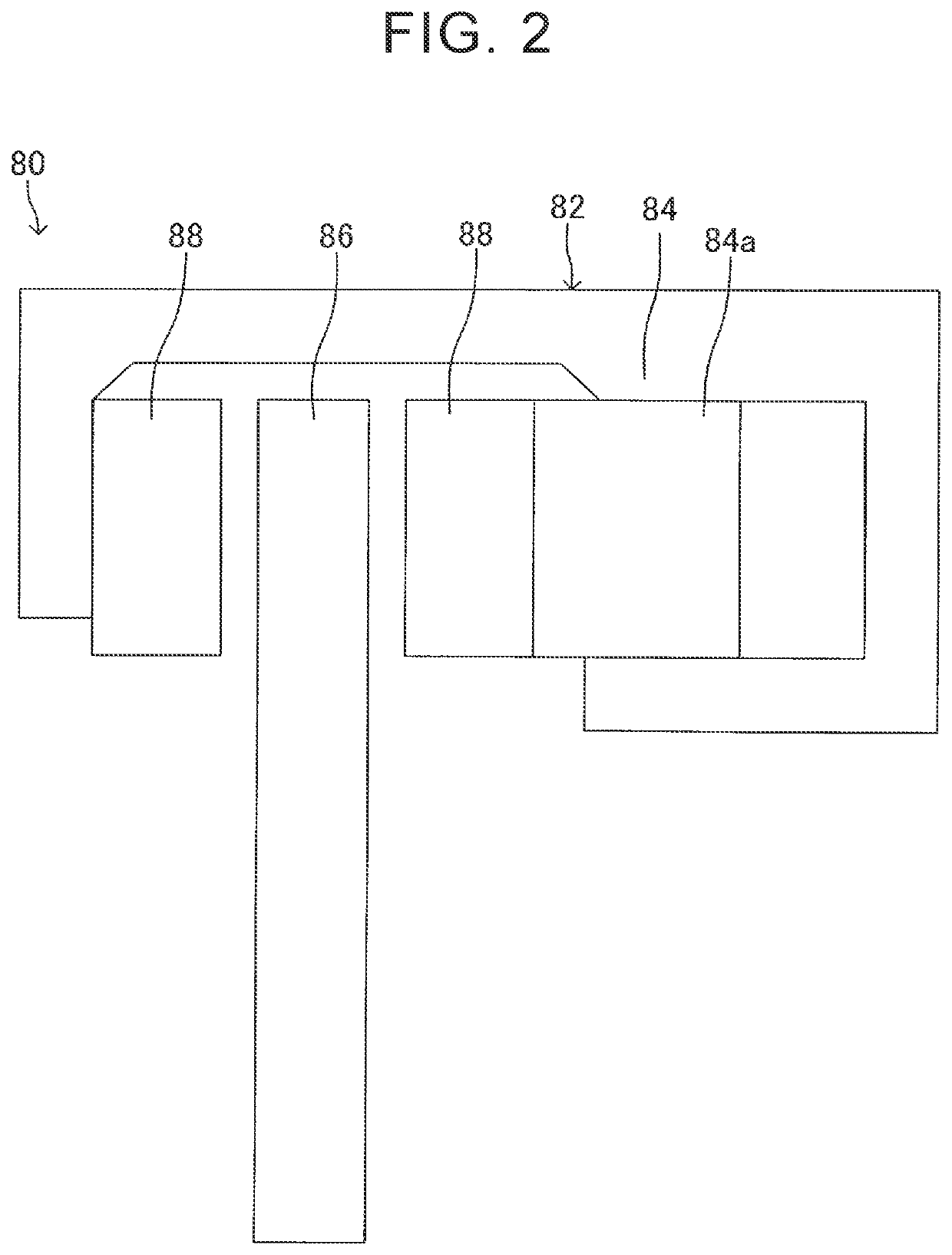
CROSS-REFERENCE TO RELATED APPLICATION[0001]This application claims priority to Japanese Patent Application No. 2019-094920 filed on May 21, 2019, incorporated herein by reference in its entirety.BACKGROUND1. Technical Field[0002]The disclosure relates to a braking force control apparatus.2. Description of Related Art[0003]Conventionally, there is known a braking device that applies braking forces to wheels of a vehicle respectively. The braking device is equipped with a fluid pressure generation mechanism that generates a fluid pressure associated with a required braking force corresponding to a braking request, as a required fluid pressure, when the braking request is made, and braking mechanisms that are provided in the wheels respectively to apply braking forces depending on the required fluid pressure to the wheels respectively (e.g., see Japanese Patent Application Publication No. 2015-182639 (JP 2015-182639 A)).SUMMARY[0004]Each of the braking mechanisms includes a rotary mem...

Claims


Application Information

Patent Timeline
IPC IPC(8): B60T8/17B60T13/66B60T1/06B60T13/16
CPCB60T8/17B60T1/065B60T13/662B60T13/165B60T13/686B60T7/042B60T13/74B60T13/146B60T8/4081B60T17/22
Inventor KAMIYA, YUSUKEKUBOTA, HAYATO
Owner TOYOTA JIDOSHA KK
Learn More