Tubular body containing SiC fiber and method for producing the same

a tubular body and fiber technology, applied in the direction of instruments, distance measurement, nuclear elements, etc., can solve the problems of thermal conductivity deterioration, tubular body energy efficiency reduction, and sic fiber may not be filled sufficiently between the sic fibers forming yarns

Active Publication Date: 2022-07-05
ADMAP
View PDF12 Cites 0 Cited by
  • Summary
  • Abstract
  • Description
  • Claims
  • Application Information

AI Technical Summary

Benefits of technology

[0008]In this aspect, a first SiC fiber layer is provided along a first groove. Therefore, the winding of the bundle of SiC fibers can be controlled, so variations in the position and thickness of the first SiC fiber layer with respect to the tubular body can be suppressed. As a result, it is easy to separate the second SiC fiber layer which is located on the outer side of the first SiC fiber layer from the first SiC fiber layer according to the position and the thickness of the first SiC fiber layer. Therefore, the first SiC fiber layer and the second SiC fiber layer do not intimately contact each other, and SiC which forms the second SiC layer is easily filled between the first SiC fiber layer and the second SiC fiber layer when the second SiC layer is formed. As a result, voids can be prevented from remaining between SiC fibers, and a tubular body containing SiC fibers having a higher thermal conductivity can be provided. In addition, the use of monolithic SiC containing SiC fibers in SiC materials for the tubular body can prevent brittle fracture of the SiC composites and provide a tubular body without continuous non-catastrophic fracture which can occur in a tubular body made only of monolithic SiC. That is, a tubular body with enhanced combined effects can be provided.
[0010]In this aspect, the thickness of the first SiC fiber layer is less than the depth of the first groove, so the first SiC fiber layer and second SiC fiber layer can be reliably spaced from each other. When the SiC fibers are wound in the first groove, the SiC fibers can be prevented from being caught by the edge portions of the first groove. As a result, the first SiC fiber layer and the second SiC fiber layer can be more reliably kept separated from each other.
[0012]In this aspect, a second groove having a depth shallower than that of the first groove can be provided in addition to the first groove. This makes it possible to control the winding of the bundles of the two SiC fibers. As a result, the first SiC fiber layer and the second SiC fiber layer can be reliably kept separated from each other.
[0013]In a fourth aspect, the first SiC layer may be sintered SiC. SiC is easy to process in a solid state before sintering. By processing and forming the first groove prior to sintering, the manufacturing costs of forming the first groove can be reduced. As a result, it is possible to provide a low-cost tubular body containing SiC fibers having a high thermal conductivity.
[0016]In this aspect, the first SiC fiber layer is formed of SiC fibers along the first groove. The second SiC fiber layer is formed with a separation from the first SiC fiber layer. The second SiC layer fills the gaps separating the first SiC fiber layer and the second SiC fiber layer, and covers the first SiC layer, the first SiC fiber layer and the second SiC fiber layer. This can prevent many voids from remaining between the SiC fibers. As a result, it is possible to provide a method of manufacturing a tubular body containing SiC fibers having a high thermal conductivity.

Problems solved by technology

If the yarns are in intimate contact with each other, the SiC material may not be sufficiently filled between the SiC fibers forming the yarns.
If the SiC precursors are insufficiently filled, many voids remain, thermal conductivity is deteriorated, and the energy efficiency of the tubular body is lowered.

Method used


Image

  • Tubular body containing SiC fiber and method for producing the same
  • Tubular body containing SiC fiber and method for producing the same
  • Tubular body containing SiC fiber and method for producing the same

Examples


Embodiment Construction

[0021]Embodiments of the present invention will be described below with reference to the drawings.

[0022](1) Overall Structure

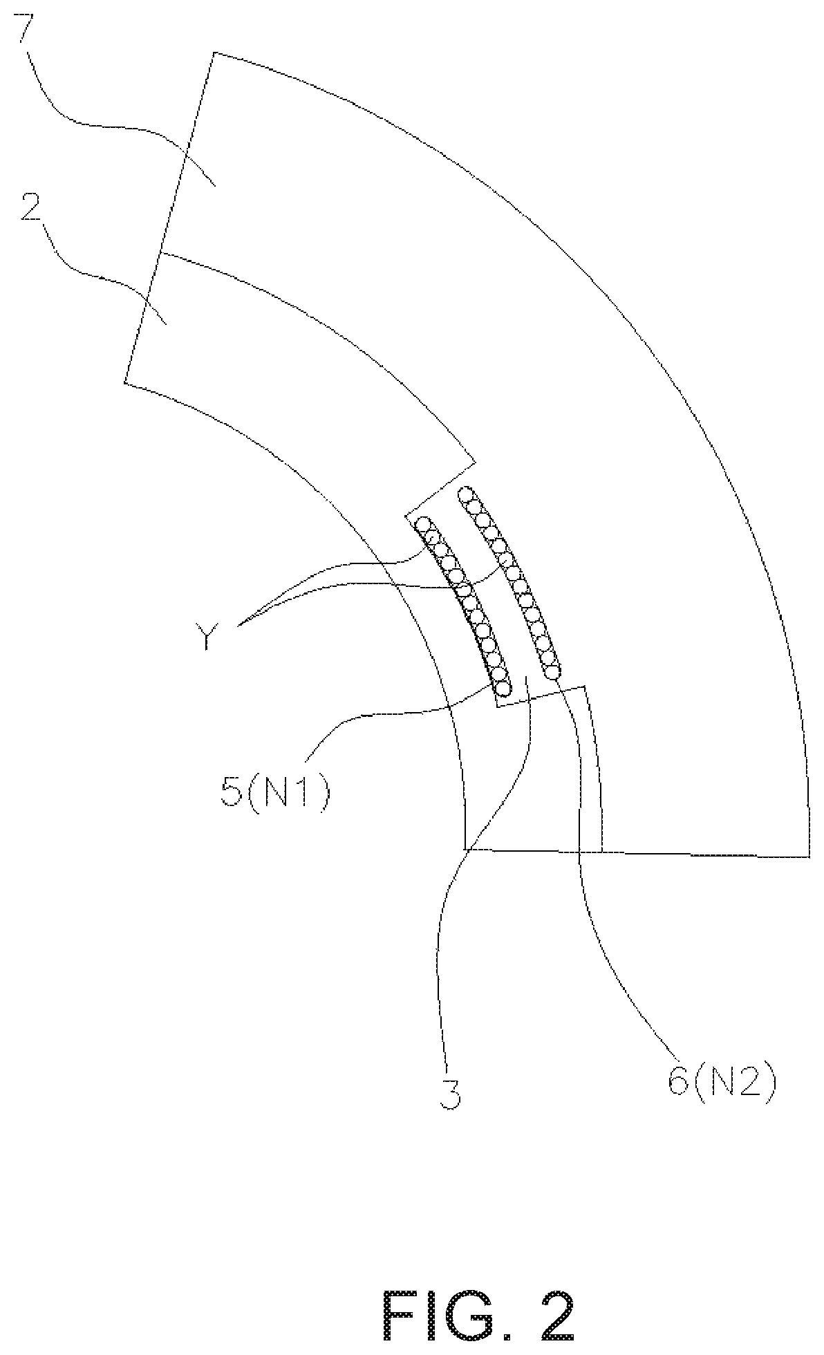
[0023]FIG. 1 is a perspective view showing the structure of a tubular body 1 containing SiC fibers. FIG. 2 is a cross-sectional view taken along line A-A of a tubular body containing SiC fibers. The A-A cross section of FIG. 2 is a cross section where a first SiC fiber layer 5 and a second SiC fiber layer 6, which will be described later, intersect with each other. As shown in FIGS. 1 and 2, the tubular body 1 includes a first SiC layer 2, a plurality of first grooves 3, and a plurality of second grooves 4 provided along the outer periphery of the first SiC layer 2 (see the broken line in FIG. 1), a first SiC fiber layer 5 made of a plurality of SiC fibers Y provided along the first grooves 3, a second SiC fiber layer 6 containing a plurality of SiC fibers Y provided along the second grooves 4, and a second SiC layer 7. In the present embodiment, if the tubula...


PUM

PropertyMeasurementUnit
thicknessaaaaaaaaaa
thicknessaaaaaaaaaa
thicknessaaaaaaaaaa

Abstract

A first SiC layer formed into a tubular shape and made of a SiC material, a first groove which spirals in one direction along the outer periphery of the first SiC layer, a first SiC fiber layer made of a plurality of SiC fibers wound along the first groove, a second SiC fiber layer made of a plurality of SiC fibers wound outside of the first SiC fiber layer in a direction different from the one direction, and a second SiC layer which is made of a SiC material and which covers the first SiC layer, the first SiC fiber layer, and the second SiC fiber layer are provided. The first SiC fiber layer and the second SiC fiber layer are separated from each other at intersections of the first SiC fiber layer and the second SiC fiber layer.

Description

CROSS-REFERENCE TO RELATED APPLICATIONS[0001]This application claims priority to Japanese Patent Application No. 2018-206259, filed on Nov. 1, 2018. The entire disclosure of Japanese Patent Application No. 2018-206259 is hereby incorporated herein by reference.BACKGROUNDTechnical Field[0002]The present invention relates to a tubular body containing SiC fibers and a method for manufacturing the sameBackground Information[0003]SiC (silicon carbide) has been proposed as a material for tubular bodies used in special environments and extreme environments where high durability is required such as in the fields of nuclear power and aerospace. SiC material s have excellent heat resistance and chemical stability, they have high thermal conductivity and mechanical strength, they are light in weight, and they have good neutron economy and low reactivity with high-temperature water. For these reasons, it is expected that a nuclear fuel cladding tube which is safer and more efficient than a conv...

Claims


Application Information

Patent Timeline
Patent Type & Authority Patents(United States)
IPC IPC(8): G21C3/07B32B1/08F16L9/04B32B5/02C04B35/565B32B3/30B32B5/12B32B18/00C04B41/87
CPCG21C3/07B32B1/08B32B3/30B32B5/02B32B5/12C04B35/565F16L9/042B32B18/00C04B41/87G21C3/06C04B35/622C04B2235/614C04B2235/616C04B2235/5244B32B5/26B32B9/005B32B2262/105B32B2307/714B32B2307/302B32B2307/306B32B2307/50B32B2597/00F16L9/00C04B41/80
Inventor KAWAHARA, FUMITOMO
Owner ADMAP
Why Eureka
Try Eureka