
Wireless communication device

a wireless communication and wireless technology, applied in the direction of cross-talk/noise/interference reduction, disturbance protection, printed circuit aspects, etc., can solve the problem that the improvement of the conventional wireless communication device is easily neglected, and achieve the effect of effectively improving the problem

Active Publication Date: 2022-04-19
AZUREWAVE TEHNOLOGIES INC
View PDF14 Cites 0 Cited by
  • Summary
  • Abstract
  • Description
  • Claims
  • Application Information

AI Technical Summary

Benefits of technology

The present invention provides a wireless communication device that improves upon conventional devices by using an insulating sheet to separate passive components from nano-metallic layers, eliminating the need for a grounding metal housing and reducing device thickness.

Problems solved by technology

However, skilled persons in this technical field have become accustomed to the configuration of the conventional wireless communication device (e.g., the grounding metal housing is installed), so that the improvement of the conventional wireless communication device is easily neglected due to the above technical prejudice.

Method used


Image

  • Wireless communication device
  • Wireless communication device
  • Wireless communication device

Examples


first embodiment

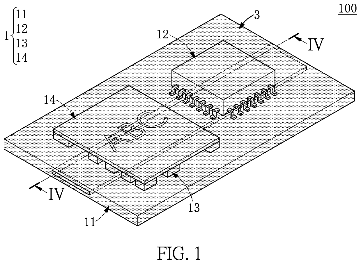
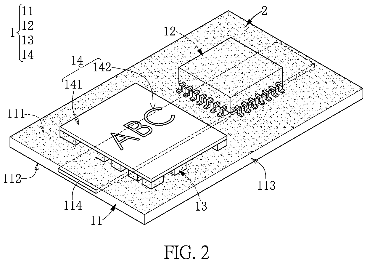
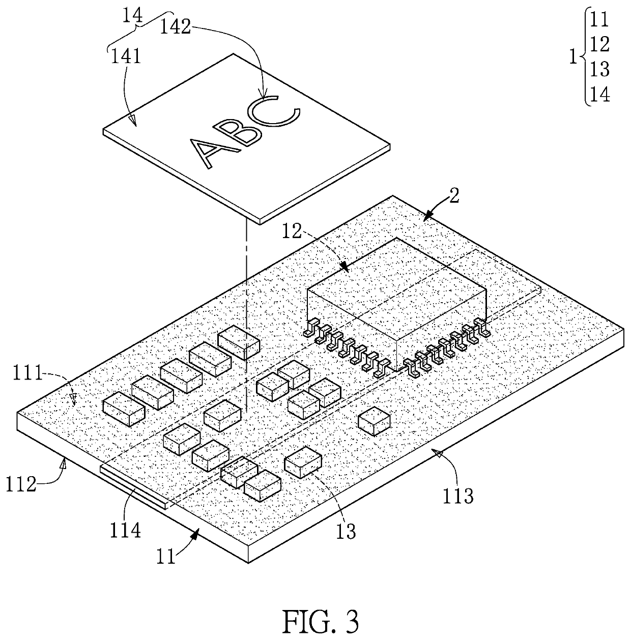
[0022]Referring to FIG. 1 to FIG. 4, a first embodiment of the present disclosure provides a wireless communication device 100 that can be a Wi-Fi module or a Bluetooth module, but the present disclosure is not limited thereto. In the present embodiment, the wireless communication device 100 includes a communication module 1, a dust and moisture resistant adhesive 2 formed on the communication module 1, and a nano-metallic layer 3 that is formed on the communication module 1 and the dust and moisture resistant adhesive 2. However, in other embodiments of the present disclosure, the wireless communication device 100 can further include an electrical connector mounted on the communication module 1.

[0023]The communication module 1 includes a circuit board 11, a communication chip 12 and a plurality of passive components 13 which are mounted on the same side of the circuit board 11, and an insulating sheet 14 that is disposed on the passive components 13. The communication module 1 in t...

second embodiment

[0040]Referring to FIG. 5 to FIG. 8, a second embodiment of the present disclosure similar to the first embodiment of the present disclosure is presented. For the sake of brevity, descriptions of the same components in the first and second embodiments of the present disclosure will be omitted herein, and the following description only discloses different features between the first and second embodiments. The different features reside in the connection relationship between the insulating sheet 14 and other components (e.g., the circuit board 11, the communication chip 12, and the passive components 13).

[0041]In the present embodiment, the insulating sheet 14 in the present embodiment is disposed on the communication chip 12 and the passive components 13, and the insulating sheet 14 can be fixed onto the communication chip 12 and the passive components 13 through an adhesive, but the present disclosure is not limited thereto. The communication chip 12 and the passive components 13 are...


PUM


Abstract

A wireless communication device is provided and includes a communication module, a dust and moisture resistant adhesive, and a nano-metallic layer. The communication module includes a circuit board, a communication chip and a plurality of passive components mounted on a carrying surface of the circuit board, and an insulating sheet that is disposed on the passive components and that has a thickness smaller than or equal to 150 μm. The dust and moisture resistant adhesive covers any electrically conductive portions of the communication module on the carrying surface. The nano-metallic layer covers the dust and moisture resistant adhesive, the communication chip, the passive components, and the insulating sheet, and is electrically coupled to a grounding portion of the circuit board. The wireless communication device does not include any grounding metal housing mounted on the circuit board.

Description

CROSS-REFERENCE TO RELATED PATENT APPLICATION[0001]This application claims the benefit of priority to Taiwan Patent Application No. 109120391, filed on Jun. 17, 2020. The entire content of the above identified application is incorporated herein by reference.[0002]Some references, which may include patents, patent applications and various publications, may be cited and discussed in the description of this disclosure. The citation and / or discussion of such references is provided merely to clarify the description of the present disclosure and is not an admission that any such reference is “prior art” to the disclosure described herein. All references cited and discussed in this specification are incorporated herein by reference in their entireties and to the same extent as if each reference was individually incorporated by reference.FIELD OF THE DISCLOSURE[0003]The present disclosure relates to a communication device, and more particularly to a wireless communication device provided wi...

Claims


Application Information

Patent Timeline
Patent Type & Authority Patents(United States)
IPC IPC(8): H05K9/00H01Q1/38H01Q1/00H01Q1/02H01Q1/22H05K1/02
CPCH01Q1/38H01Q1/002H01Q1/02H01Q1/2283H05K1/0218H05K9/0026H05K9/0084H05K3/284H05K1/0216H05K2203/1366H05K1/0243H05K2201/0715H05K2201/09872
Inventor LIAO, CHIH-HAOHUANG, HSIN-YEHWU, SHU-HAN
Owner AZUREWAVE TEHNOLOGIES INC
Learn More