
Method for producing an electrical heating device

a heating device and heating element technology, applied in the direction of heating element shapes, metal working devices, manufacturing tools, etc., can solve the problems of insufficient strength of jacket material, inability to implement this approach in production processing,

Active Publication Date: 2022-03-22
TUERK & HILLINGER
View PDF6 Cites 0 Cited by
  • Summary
  • Abstract
  • Description
  • Claims
  • Application Information

AI Technical Summary

Benefits of technology

[0013]In this way, the compression of the electrical heating device can be achieved with high precision and with process-reliable, highly reproducible results.
[0022]In one preferred embodiment of the invention, it is provided that the arrangement of the tubular sections in the sections to be compressed is realized for at least one tubular section such that it is pushed onto the sleeve so that it surrounds the section to be compressed in the radial direction. This is associated not only with especially simple, precise positioning, but also enables a high-precision localized application of force in the compression process, especially through the use of a compression tool that applies force, at least at the start of the compression process, mainly on the pushed-on tubular section.
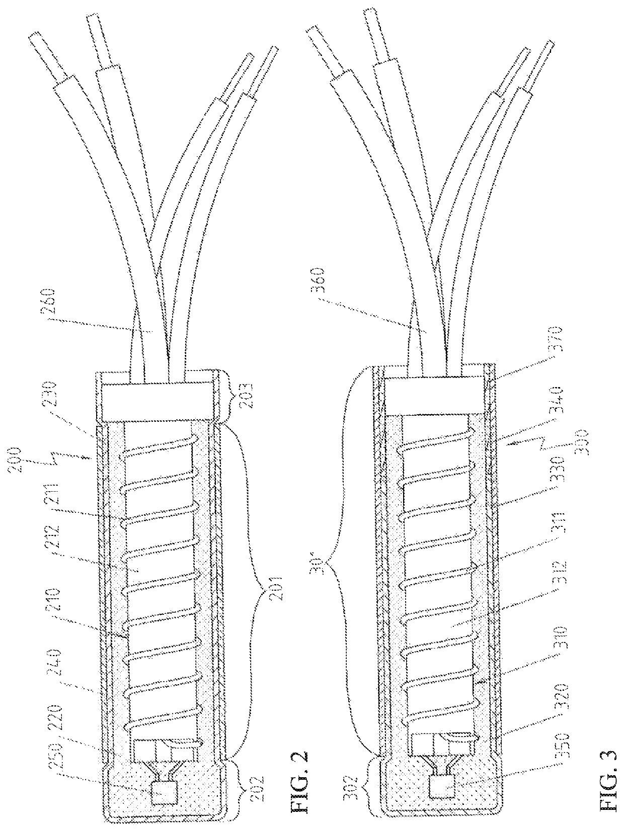
[0026]Therefore, because a tubular section is arranged on the sleeve so that it projects past the sleeve, in particular, past an end side of the sleeve, in particular, the possibility is created to produce the electrical heating device with a closed area with defined properties. For example, in this way, an undesired flow of heat in the direction toward the connections of the electrical heating device can be largely prevented. In particular, it is possible that another tube that concentrically extends the sleeve is arranged in the area of the tubular section projecting past the sleeve.
[0027]It can be advantageous to rework the bottom of the sleeve after the compression process, especially so that a flat end surface is produced, which can be realized, for example, by a metal-cutting process on the bottom. Simultaneously, however, it is to be noted that due to the method according to the invention, for an adapted selection of the degree of compression of the respective areas, in many cases, a deformation of the end face during the compression process can be avoided, so that such a reworking step becomes unnecessary.

Problems solved by technology

However, up to now the implementation of this approach in production processing has proven not to be very reliable.
In other electrical heating cartridges, there are production problems in that the strength of the jacket material is not strong enough, for example, when a sleeve made from high-purity titanium is desired for medical applications.

Method used


Image

  • Method for producing an electrical heating device
  • Method for producing an electrical heating device
  • Method for producing an electrical heating device

Examples


Embodiment Construction

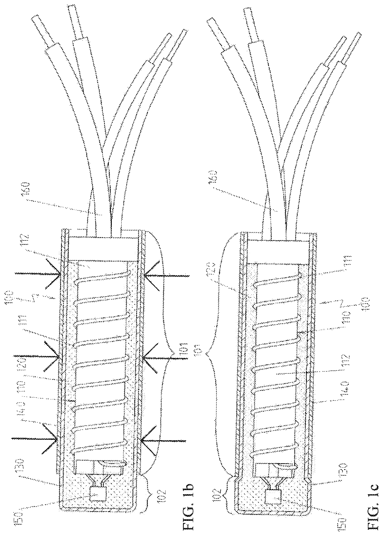
[0041]If arrows are drawn in figures that still show non-compressed electrical heating devices, these arrows indicate the direction of the compression of the system or method.

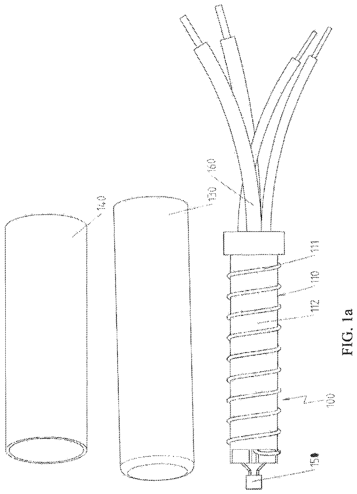
[0042]FIG. 1a shows the partially preconfigured components of an electrical heating device 100 prepared for performing the additional processing steps in accordance with a first preferred embodiment. This figure shows, in particular, the electrical heating element 110 constructed as coil body 112 wound with a resistance wire 111, and the sleeve 130 made from copper and the tubular section 140 made from stainless steel. Naturally, copper and stainless steel have their own strength values, and the strength of stainless steel is higher than that of copper.

[0043]The electrical heating element 110 is also preconfigured here to the extent that an electronic component 150, namely here a temperature sensor, is arranged on the coil body on the end side and a connection to connecting wires 160 has already been produced.

[...


PUM

PropertyMeasurementUnit
strengthaaaaaaaaaa
processing reliabilityaaaaaaaaaa
resistanceaaaaaaaaaa

Abstract

A method for producing an electrical heating device with the steps of preparing a sleeve from a first material that has a first strength; arranging an electrical heating element in the sleeve; arranging of a filler material in the sleeve, so that parts of the electrical heating element carrying current are electrically isolated from the sleeve and the position of the electrical heating element in the sleeve is fixed, and at least section-wise compression of the sleeve, of the electrical heating element is arranged in sections of the sleeve that are compressed, and of the filler material arranged in sections of the sleeve that are compressed, wherein, before the completion of the at least section-wise compression of the sleeve, in sections to be compressed, a tubular section is arranged that is made from a second material that has a second strength higher than the first strength.

Description

CROSS-REFERENCE TO RELATED APPLICATIONS[0001]This application claims priority to German Patent Application No. 10 2018 109 306.3, filed on Apr. 19, 2018. The entirety of the aforementioned application is incorporated herein by reference in its entirety.BACKGROUND OF THE INVENTION[0002]Electrical heating devices that have a sleeve with an electrical heating element arranged therein, whose parts carrying current are electrically isolated from the sleeve, are a standard mechanism for the electrical heating of objects and / or media.[0003]For many actual embodiments of such electrical heating devices, there is, on one hand, the desire for the highest possible compression, in order to guarantee the best possible heat conduction from the electrical heating device to the sleeve that is brought into contact with the object or medium, while, simultaneously, the applicable compression must be limited, at least locally, for example, because other, pressure-sensitive elements, e.g., electronic co...

Claims


Application Information

Patent Timeline
Patent Type & Authority Patents(United States)
IPC IPC(8): B28B23/00H05B3/46H01C17/02B23P11/00
CPCB28B23/00B23P11/005H01C17/02H05B3/46H05B3/02H05B3/18H05B3/54H05B3/58H05B3/48
Inventor SCHLIPF, ANDREAS
Owner TUERK & HILLINGER
Learn More