
Scalable, electro-optically induced force system and method

a technology of electro-optically induced force and scalable technology, applied in scanning probe techniques, instruments, nuclear engineering, etc., can solve the problems of limited achievable manipulation force, current techniques operate, and none of these are practically applicable to larger samples or efficiently use laser light to accomplish manipulation, etc., to achieve the desired effect and high density

Active Publication Date: 2022-02-01
GERMANN GEOFFREY JAMES
View PDF1 Cites 1 Cited by
  • Summary
  • Abstract
  • Description
  • Claims
  • Application Information

AI Technical Summary

Benefits of technology

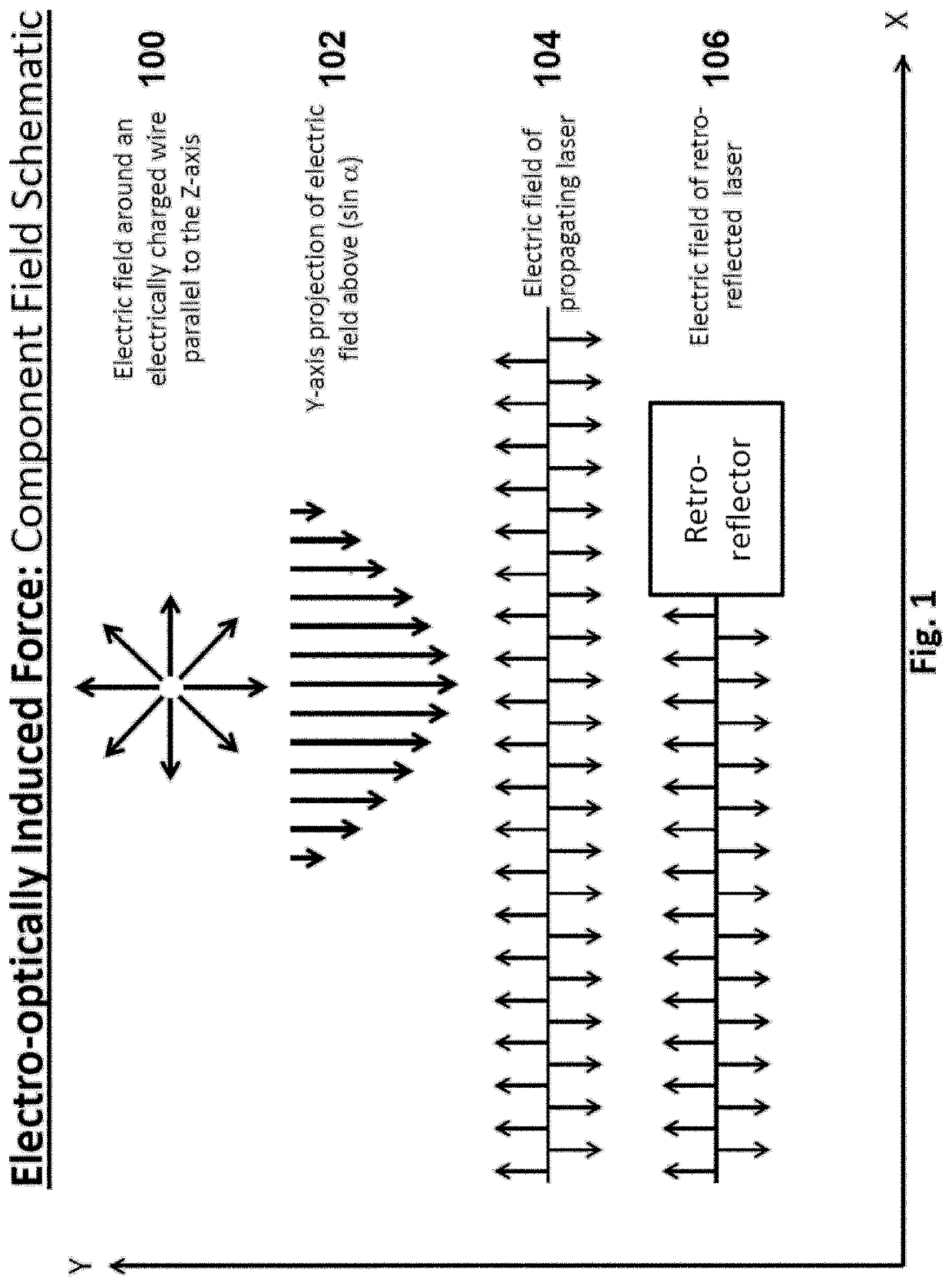
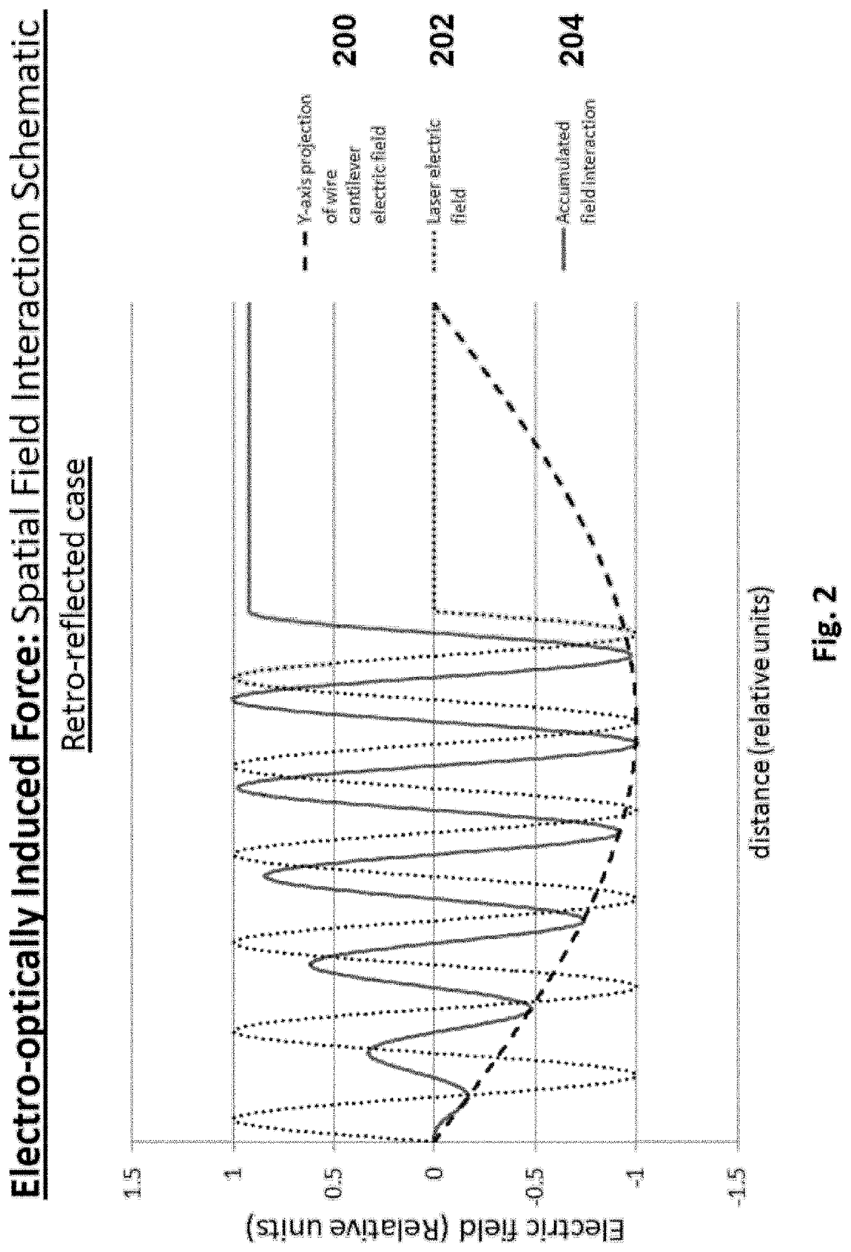
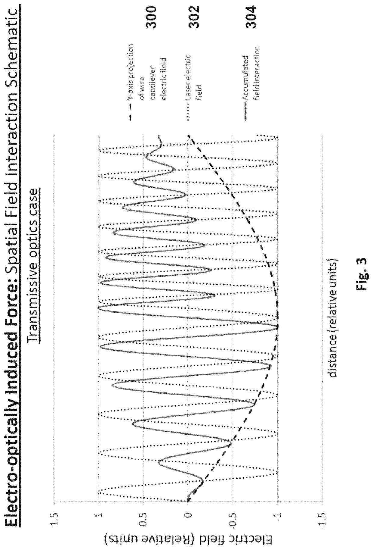
This patent describes a method for creating a powerful electric field using a laser and a signal generator operating at the same frequency. By constructing a field carrier array with high density and small feature spacing, a million or more field interaction locations can be achieved. This means that even if the electric field of the laser and the electric field near the charge carrier are in opposition only a small fraction of the time, the integrating effect can result in a significant accumulated force between the two electric fields. This technology has applications in various fields such as optics, electronics, and biology.

Problems solved by technology

All of these techniques allow for control of small samples with laser light, but none of these is practically applicable to larger samples or efficiently uses the laser light to accomplish the manipulation.
One of the difficulties is that many of the current techniques operate by inducing an electric charge polarization in the sample.
This limits the achievable manipulation force.
Also, these techniques commonly require the laser to be focused on the target sample, limiting the length of interaction and thus the efficiency with which the laser energy is coupled into translation.
Other techniques rely on the transfer of photon momentum in the optical scattering process, but this is extremely inefficient as photons at commonly accessible wavelengths have very little mass.

Method used


Image

  • Scalable, electro-optically induced force system and method
  • Scalable, electro-optically induced force system and method
  • Scalable, electro-optically induced force system and method

Examples


Embodiment Construction

[0046]Reference will now be made in detail to some embodiments of the invention, examples of which are illustrated in the accompanying drawings.

[0047]The present invention allows for the application of laser light to achieve a scalable electromagnetically induced force to samples of greater mass than previous techniques and for more efficient use of the applied laser light. The sample upon which the force is realized must be of specific construction to support an electric charge distribution and variation to achieve a net repulsion or attraction with the laser light. Using this approach the laser need not be focused on the sample nor induce an electric charge polarization on the sample. This allows the force to be integrated over a longer distance, greatly improving the efficiency with which the laser energy is used and increasing the mass amenable to manipulation by the techniques of the present invention.

[0048]Several recent advancements have driven this invention. First, the lase...


PUM

PropertyMeasurementUnit
frequencyaaaaaaaaaa
frequencyaaaaaaaaaa
lengthaaaaaaaaaa

Abstract

A technique is disclosed for electro-optically inducing a force to fabricated samples and / or devices with laser light. The technique uses the interaction of the oscillating electric field of the laser beam in opposition with the electric field produced by an appropriate electric charge carrier to achieve a net repulsive (or attractive) force on the component holding the electric charge. In one embodiment, force is achieved when the field near the charge carrier is modulated at a subharmonic of the electric field oscillation frequency of the laser and the relative phases of the light field and electric charge carrier field are controlled to provide optimal repulsion / attraction. The effect is scalable by applying the technique to an array of charge carrier fields sequentially as well as using higher power lasers and higher carrier field voltages.

Description

CROSS REFERENCE TO RELATED APPLICATIONS[0001]This application is a continuation-in-part of, and claims the benefit under 35 U.S.C. § 120 from, nonprovisional U.S. patent application Ser. No. 16 / 420,162, entitled “Scalable, Electro-Optically Induced Force System And Method”, filed May 23, 2019. Application Ser. No. 16 / 420,162, in turn, is a continuation-in-part of, and claims the benefit under 35 U.S.C. § 120 from, nonprovisional U.S. patent application Ser. No. 15 / 959,280, entitled “Scalable, Electro-Optically Induced Force System And Method”, filed Apr. 23, 2018, now U.S. Pat. No. 10,354,772. Application Ser. No. 15 / 959,280, in turn, is a continuation-in-part of, and claims the benefit under 35 U.S.C. § 120 from, nonprovisional U.S. patent application Ser. No. 15 / 406,737, entitled “Scalable, Electro-Optically Induced Force System And Method”, filed Jan. 15, 2017, now U.S. Pat. No. 9,984,782. The subject matter of each of the foregoing documents is expressly incorporated herein by r...

Claims


Application Information

Patent Timeline
Patent Type & Authority Patents(United States)
IPC IPC(8): G21K1/00G02F1/00G21K5/02H03L7/00H01S3/108G01Q80/00H05H3/04
CPCG21K1/003G01Q80/00G02F1/0018G21K5/02H01S3/108H03L7/00H05H3/04
Inventor GERMANN, GEOFFREY JAMES
Owner GERMANN GEOFFREY JAMES
Learn More