
Display device and backlight module

a backlight module and display device technology, applied in non-linear optics, instruments, optics, etc., can solve the problems of unsatisfactory visual effects of images displayed by above contrast ratio, affecting viewing quality, and unsatisfactory ratio, so as to reduce light emissivity, reduce brightness unevenness, and high reflectivity

Active Publication Date: 2022-01-04
TCL CHINA STAR OPTOELECTRONICS TECH CO LTD
View PDF10 Cites 0 Cited by
  • Summary
  • Abstract
  • Description
  • Claims
  • Application Information

AI Technical Summary

Benefits of technology

[0006]An embodiment of the present disclosure provides a display device and a backlight module, which is configured to improve a problem of uneven display of brightness in a surface of the backlight module due to a brightness of the backlight module close to a power inlet being greater than a brightness of the backlight module away from the power inlet.
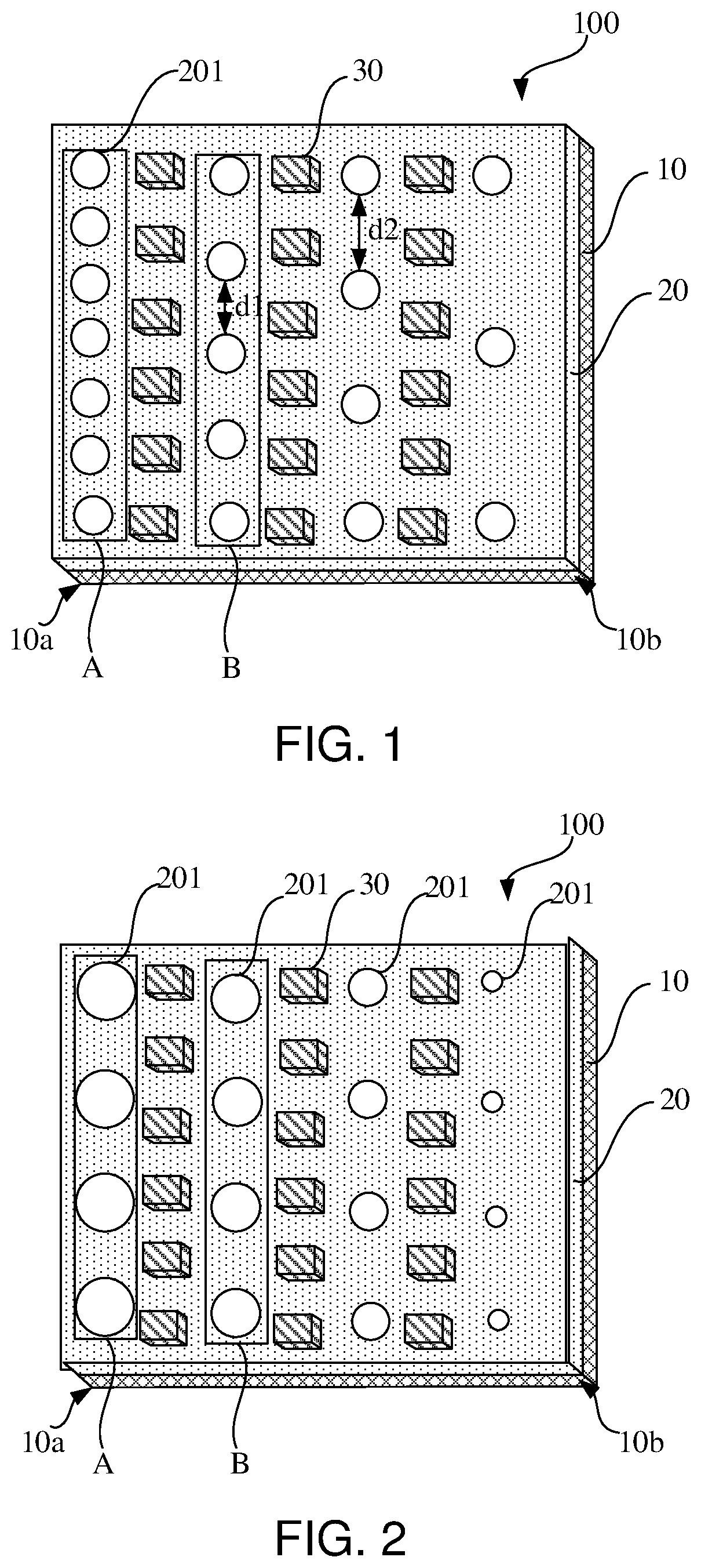
[0027]A current of mini light-emitting diode (LED) backlight modules is injected through a single aspect. As a distance of wirings increases, IR drop will occur, so that the brightness of the backlight module close to the power inlet is greater than the brightness of the backlight module away from the power inlet, resulting in an uneven display of the brightness in the surface of the backlight module. The backlight module provided by the present disclosure is provided with the ink layer with hollow-carved units arranged on the substrate so that the light emitted by the light-emitting unit and light reflected by the optical film are partially absorbed by the hollow-carved unit. Since the hollow-carved units are arranged in a gradual arrangement, which is configured to reduce emissivity of light, a reflectance of light at a light intense position is less than a reflectance of the light at a light weak position, thereby relieving the problem of the uneven brightness of the brightness in the surface of the backlight module.
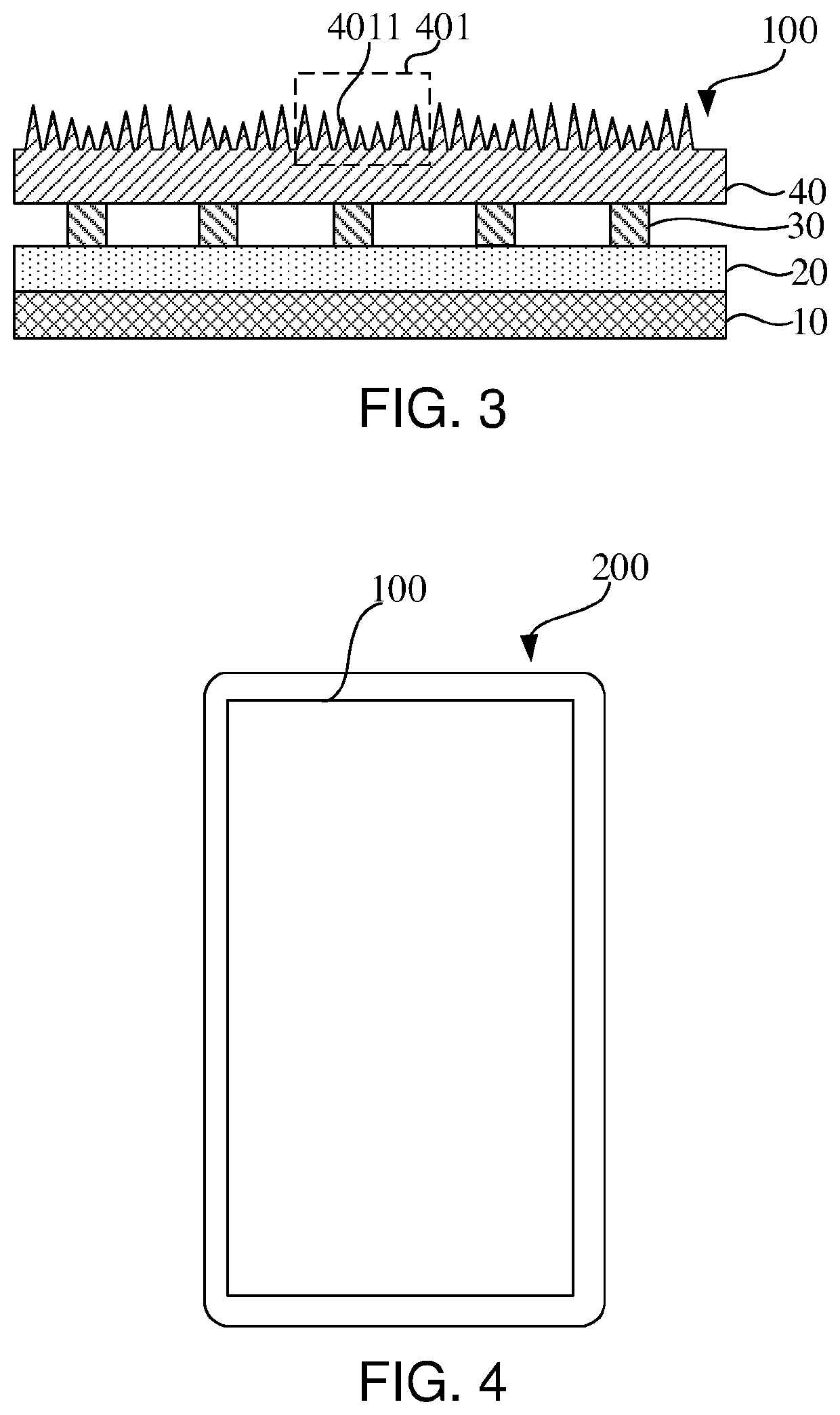
[0028]In addition, the present disclosure provides a white ink layer on the substrate. Since the ink layer has a high reflectivity, it can reflect the light emitted by the light-emitting unit to the optical film. The ink layer can also reflect the light reflected by the optical film to the ink layer again to the optical film, thereby improving light utilization rate. Moreover, in the present disclosure, the ink layer is directly disposed on the substrate, which can replace current reflection sheets and save production cost.

Problems solved by technology

However, due to limitations of various actual processes, materials, etc., a contrast ratio can reach up to 5000:1, and a visual effect of images displayed by above contrast ratio is unideal.
However, because a number of partitions is limited by light-emitting diode pitch (LED interval), etc., a halo often occurs in a display effect, which affects viewing quality.
As a distance of wirings increases, IR drop will occur, so that a brightness of the backlight module close to a power inlet is greater than a brightness of the backlight module away from the power inlet, resulting in a problem of uneven display of the brightness in a surface of the backlight module.

Method used


Image

  • Display device and backlight module
  • Display device and backlight module

Examples


Embodiment Construction

[0034]In order to make objectives, technical solutions, and advantages of the present disclosure clearer, the present disclosure will be further described in detail below with reference to drawings. Please refer to the drawings, in which the same component symbols represent the same components, following description is based on the specific embodiment of the present disclosure shown, which should not be considered as limiting other specific embodiments of the present disclosure not detailed here.

[0035]In descriptions of the present disclosure, it should be noted that, orientations or position relationships indicated by the terms, such as “center”, “longitudinal”, “transverse”, “length”, “width”, “thickness”, “upper”, “lower”, “front”, “back”, “left”, “right”, “vertical”, “horizontal”, “top”, “bottom”, “inside”, “outside”, “clockwise”, “counterclockwise”, etc. are based on the orientations or position relationships shown in the drawings. These are only convenience for describing the ...


PUM

PropertyMeasurementUnit
densityaaaaaaaaaa
areaaaaaaaaaaa
light transmittanceaaaaaaaaaa

Abstract

The present invention provides a display device and a backlight module. The backlight module includes a substrate, an ink layer, and a plurality of light-emitting units, wherein the substrate includes a first end and a second end oppositely arranged, the ink layer is disposed on the substrate, the ink layer includes a plurality of hollow-carved units arranged gradually from the first end to the second end, and at least two light-emitting units are disposed on the ink layer in an array arrangement.

Description

FIELD OF INVENTION[0001]The present disclosure relates to the field of display technology, and more particularly, to a display device and a backlight module.BACKGROUND OF INVENTION[0002]A backlight of traditional low-end liquid crystal display devices turns on when light is turned on, and turns off when the light is turned off. A brightness and darkness adjustment of final images depends on a liquid crystal display layer blocking the light. However, due to limitations of various actual processes, materials, etc., a contrast ratio can reach up to 5000:1, and a visual effect of images displayed by above contrast ratio is unideal. Traditional mid-range liquid crystal display devices will also achieve local dimming products with dozens to hundreds of partitions, which can better improve a certain contrast. However, because a number of partitions is limited by light-emitting diode pitch (LED interval), etc., a halo often occurs in a display effect, which affects viewing quality.[0003]Hen...

Claims


Application Information

Patent Timeline
Patent Type & Authority Patents(United States)
IPC IPC(8): G02F1/13357
CPCG02F1/133611G02F1/133603G02F1/133606G02F1/133605G02F1/133612
Inventor FU, LINLINLI, DEHUAZHANG, XIN
Owner TCL CHINA STAR OPTOELECTRONICS TECH CO LTD
Learn More