Organic polymer aerogels comprising microstructures
an organic polymer and aerogel technology, applied in the field of aerogels, can solve the problems of high cost, time-consuming, complicated processes, drying or super-drying, etc., and achieve the effects of enhancing thermal and mechanical properties, reducing the average pore size, and strengthening the aerogel polymer matrix
- Summary
- Abstract
- Description
- Claims
- Application Information
AI Technical Summary
Benefits of technology
Problems solved by technology
Method used
Image
Examples
example 1
Polyimide Aerogels with Dispersed Microstructures
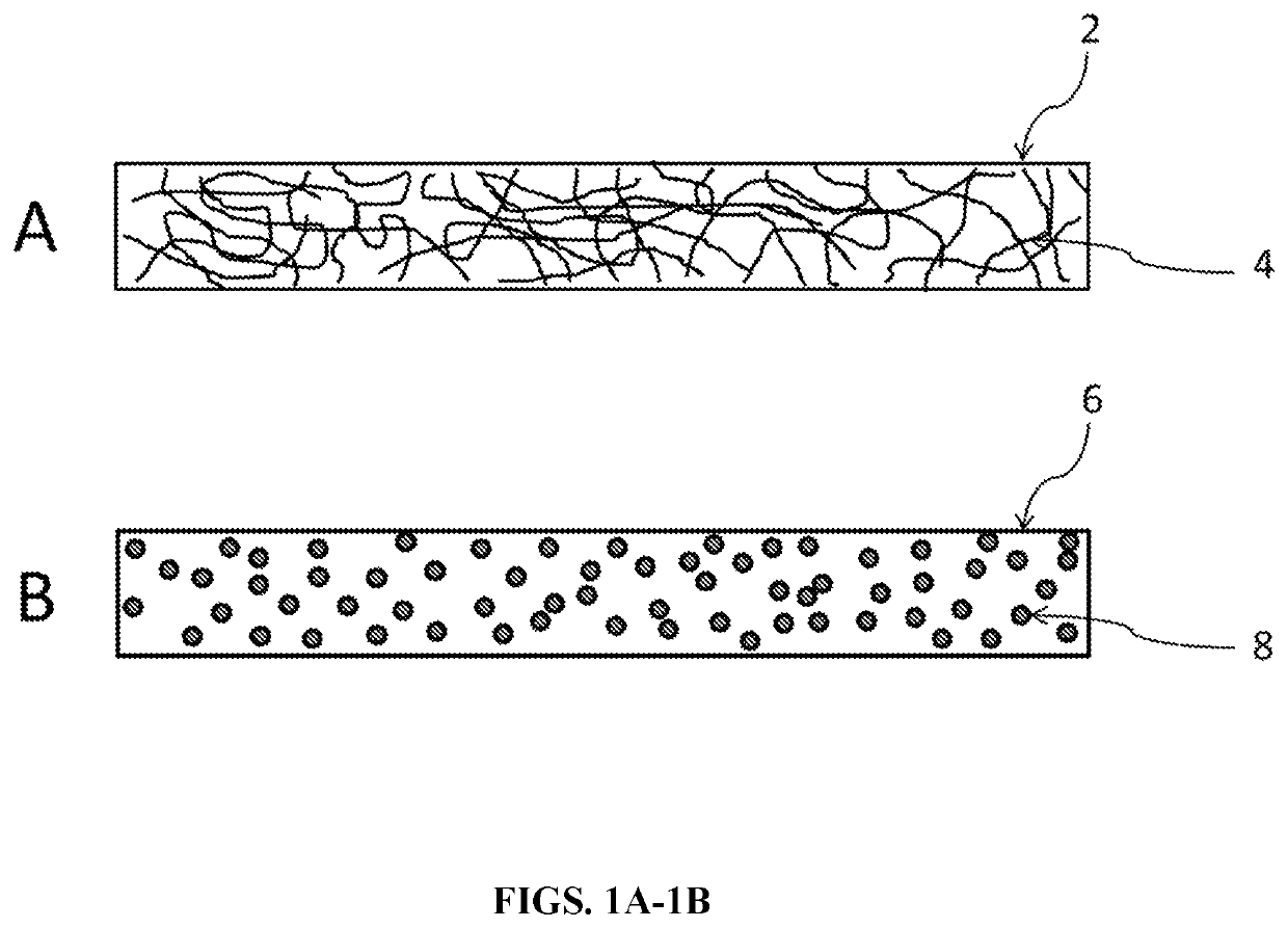
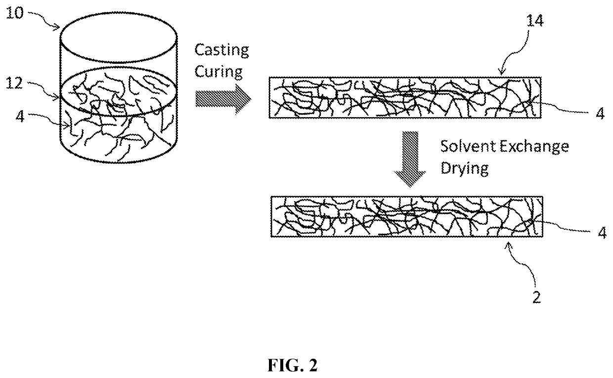
[0103]Polyimide aerogels were prepared in which aramid fibers, PTFE particles, or polyimide aerogel powders were dispersed. The aramid fibers used were Twaron fibers from Teijin Chemicals Company (Japan). Two different lengths of fibers were used: “short” fibers, which had a nominal length of 0.25 mm and a measured average length of 0.291 mm (n=87), and “long” fibers, which had a nominal length of 1.5 mm and a measured average length of 1.56 mm (n=8). The short fibers had a measured average diameter of 13.89 μm, and the long fibers had a measured average diameter of 14.86 μm.
[0104]The PTFE particles used were Ultraflor™ UF-8TA PTFE powder from Laurel Products. The UF-8TA PTFE particle has 400 nm spherical primary particles with hydrophilic macromolecules pinned to the surface.
[0105]The aerogel powder used was Aerozero® powder from Blueshift. The Aerozero® powder is a 100% polyimide powder made from polyimide aerogel material. The Aero...
example 2
Prophetic Example
Mechanical Properties of Polymer Aerogels with Dispersed Polymeric Microstructures
[0108]Organic polymer aerogels comprising polymeric microstructures will be produced by methods similar to those in Example 1. The thermal conductivity of the aerogels will be measured at a mean temperature of 20° C. and 13.8 kPa pressure using a heat flow meter. It is expected that the thermal conductivity measured in this way will be between about 15 and 40 mW / m·K.
[0109]The ultimate tensile strength (UTS) and modulus will be measured at 23° C. in the machine direction and in the cross direction according to American Standard Testing Method (ASTM) ASTM D5034 Standard Specification for Breaking Force and Elongation of Textile Fabrics (Grab Method). It is expected that the machine direction UTS will be between about 4.5 and 5.5 MPa, the machine direction modulus will be between 40 and 60 MPa, the cross direction UTS will be between 1.5 and 2.5 MPa, and the cross direction modulus will b...
example 3
Preparation of Highly Branched Polyimide Resin
[0114]To prepare a highly branched polyimide resin, a reaction vessel with a mechanical stirrer and a water jacket was employed. The flow of the water through the reaction vessel jacket was adjusted to maintain temperature in the range of 20-28° C. The reaction vessel was charged with dimethylsulfoxide (DMSO) (108.2 lbs. 49.1 kg), and the mechanical stirrer speed was adjusted to 120-135 rpm. 1,3,5-tris(4-aminophenoxy) benzene (TAPOB, 65.03 g) was added to the solvent. To the solution was added 4,4′-diamino-2,2′-dimethylbiphenyl (DMB, 1,080.96 g), followed by 4,4′-oxydianiline (ODA, 1,018.73 g). A first portion of BPDA (1,524.71 g) was added. After stirring for 20 minutes, a sample of the reaction mixture was analyzed for viscosity. A second portion of BPDA (1,420.97 g) was added, and the reaction mixture was stirred for 20 additional minutes. A sample of the reaction mixture was analyzed for viscosity. A third portion of BPDA (42.81 g) w...
PUM
| Property | Measurement | Unit |
|---|---|---|
| pore size distribution | aaaaa | aaaaa |
| pore size distribution | aaaaa | aaaaa |
| diameter | aaaaa | aaaaa |
Abstract
Description
Claims
Application Information
 - R&D
- Intellectual Property
- Life Sciences
- Materials
- Tech Scout
- Unparalleled Data Quality
- Higher Quality Content
- 60% Fewer Hallucinations
Browse by: Latest US Patents, China's latest patents, Technical Efficacy Thesaurus, Application Domain, Technology Topic, Popular Technical Reports.
© 2025 PatSnap. All rights reserved.Legal|Privacy policy|Modern Slavery Act Transparency Statement|Sitemap|About US| Contact US: help@patsnap.com


