
Chain conveyor curve

a conveyor curve and chain technology, applied in the direction of conveyors, transportation and packaging, etc., can solve the problems of not being able to move through straight parts of the conveying system, dedicated conveyor chains cannot move in the bend, and ordinary conveyor chains are not suitable for being guided through the curve, so as to reduce friction and wear.

Active Publication Date: 2021-11-30
JONGE POERINK CONVEYORS
View PDF14 Cites 0 Cited by
  • Summary
  • Abstract
  • Description
  • Claims
  • Application Information

AI Technical Summary

Benefits of technology

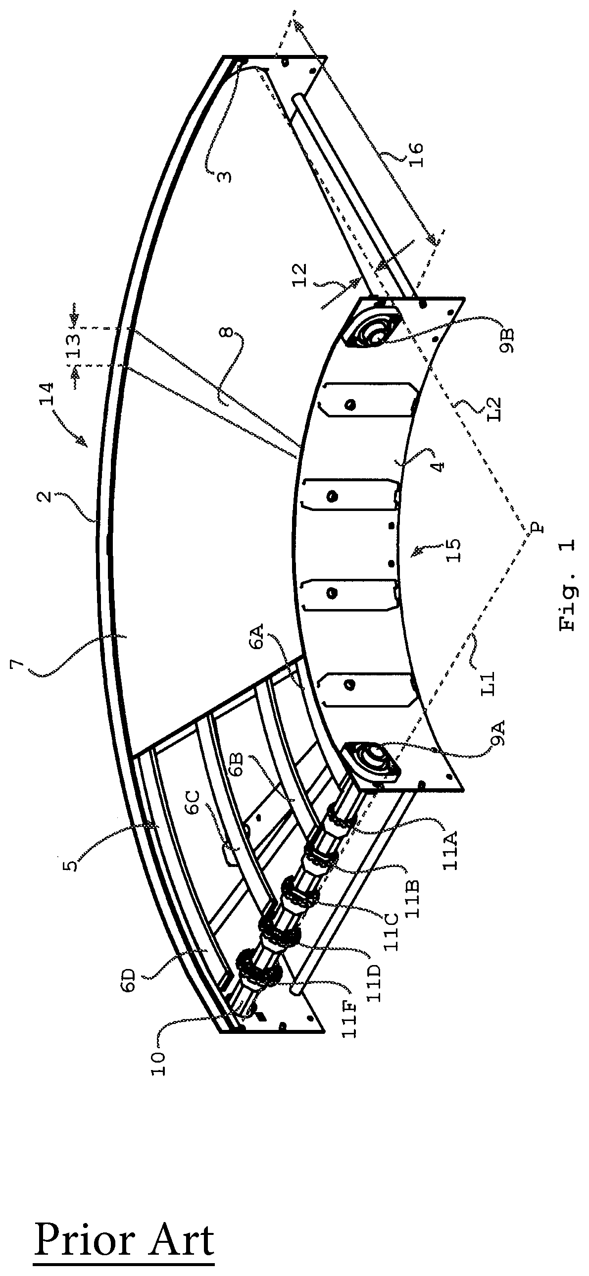
[0016]This substantially equal contact angle is configured in order to have the individual tracks move with a corresponding angular speed through the curve. Thus, any product transported on the conveyor curve will experience a smooth transport, where speed differences between the separate individual conveyor tracks is reduced or absent. In this way products experience limited forces induced by the individual conveyor tracks moving relative to each other.
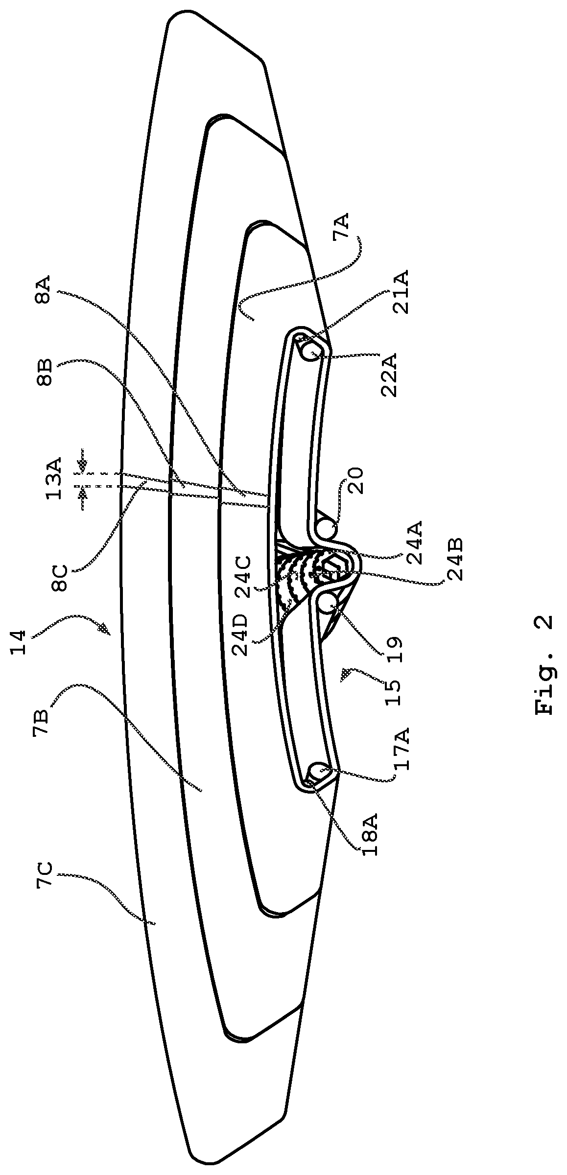
[0032]The conveyor chain is substantially borne by the hinging pins, moving over the guiders. Both in the curves and in the transport part of the individual conveyor tracks, the chains may be guided by the hinging pins sliding over guiders. This can reduce the friction forces and wear as indicated herein above.

Problems solved by technology

Thus below a specific radius, ordinary conveyor chains are not suitable for being guided through the curve.
Thus, this dedicated conveyor chain can only move in the bend, and is not suited to move through straight parts of the conveying system.
A serious draw back of these chains is that when broader chains are needed, the width of the individual chain links at the outer curve side of the chain tend to get relative large, resulting in a bumpy, ratcheting unsmooth transfer, a phenomenon also known as the polygon effect.
Yet when broad conveyor chains are used, the outer side of the conical member needs a larger diameter and thus more space at the outside of the bend than at the inside, such that gaps between feed in and offtake conveyors is wedge shaped.
Thus, these conveyors are only practical below a maximal conveyor track width.
As a result, these conveyors can be a limiting factor in the output volume of a production line in which these conveyors are applied.

Method used


Image

  • Chain conveyor curve
  • Chain conveyor curve
  • Chain conveyor curve

Examples


Embodiment Construction

[0044]The figures represent specific exemplary embodiments of the inventions and should not be considered limiting the invention in any way or form. Throughout the description and the figures the same or corresponding reference numerals are used for the same or corresponding elements.

[0045]The term ring-shaped is to be considered as, yet not to be seen as limited to an open through-going space surrounded by material, irrespective of the shape. Thus the material may be in the shape of a ring around the through going space, in the shape of an oval, a square, a long hole and / or any specific form suited for the purpose.

[0046]FIG. 1 depicts a schematic perspective view of a conventional curved path conveyor 1 for small radius turns. The conveyor 1 comprises a frame 2 having two guiding edges 3 and 4. Guiding edge 3 is located on the curve outside 14 and guiding edge 4 is located on the curve inside 15. In between the guiding edges 3 and 4 is located a support surface 5, comprising a set ...


PUM


Abstract

The invention relates to a transport conveyor curve including a multitude of parallel curved tracks, wherein the separate parallel tracks are driven by a conical drive, wherein the contact angle of each of the individual tracks with the conical drive is substantially equal in comparison to the contact angle of the other individual tracks.

Description

CROSS-REFERENCE TO RELATED APPLICATIONS[0001]This application is the United States national phase of International Application No. PCT / NL2019 / 050126 filed Feb. 27, 2019, and claims priority to The Netherlands Patent Application No. 2020605 filed Mar. 16, 2018, the disclosures of which are hereby incorporated by reference in their entirety.BACKGROUND OF THE INVENTION1. Field of the Invention[0002]The invention relates to a chain conveyor curve.[0003]More specifically, the invention relates to a chain conveyor curve with a small curvature radius. These curves typically have their own dedicated chain, spanning typically only the curve and thus having a transfer at the intake and offtake ends of the chain to straight or less curved sections of a conveying system.2. Discussion of the Related Art[0004]In the art, conveyors are frequently used for transportation of bottles, cans, various kinds of good, such as edible products, potable products and or other goods. When the tracks or chains ...

Claims


Application Information

Patent Timeline
Patent Type & Authority Patents(United States)
IPC IPC(8): B65G21/16B65G15/10B65G17/38B65G23/04B65G23/12B65G17/08B65G21/22B65G23/06B65G15/02
CPCB65G21/16B65G15/10B65G17/086B65G17/38B65G21/22B65G23/04B65G23/06B65G23/12B65G15/02
Inventor HOFF, EGBERT GERRIT
Owner JONGE POERINK CONVEYORS
Learn More