Eureka AIR delivers breakthrough ideas for toughest innovation challenges, trusted by R&D personnel around the world.

Sheet-conveying mechanism

a technology of conveying mechanism and sheet, which is applied in the direction of transportation and packaging, thin material processing, article separation, etc., can solve the problems of frequent occurrence of sheet jam, difficult film member to guide a sheet along, and sheet jams with increased frequency, so as to achieve smooth transportation and smoother transportation

Inactive Publication Date: 2006-08-17
SHARP KK
View PDF5 Cites 19 Cited by
  • Summary
  • Abstract
  • Description
  • Claims
  • Application Information

AI Technical Summary

Benefits of technology

[0014] A guiding portion such as the arm of the torsion coil spring extends to the movable member that faces the rotation roller, so as to bridge a gap between the arm and the movable member. A sheet is thus transported smoothly. When the elastic member (i.e., the sheet transport guide) is curved according to a radius of curvature of a sheet transport path, the sheet transport guide allows a sheet to be transported more smoothly.
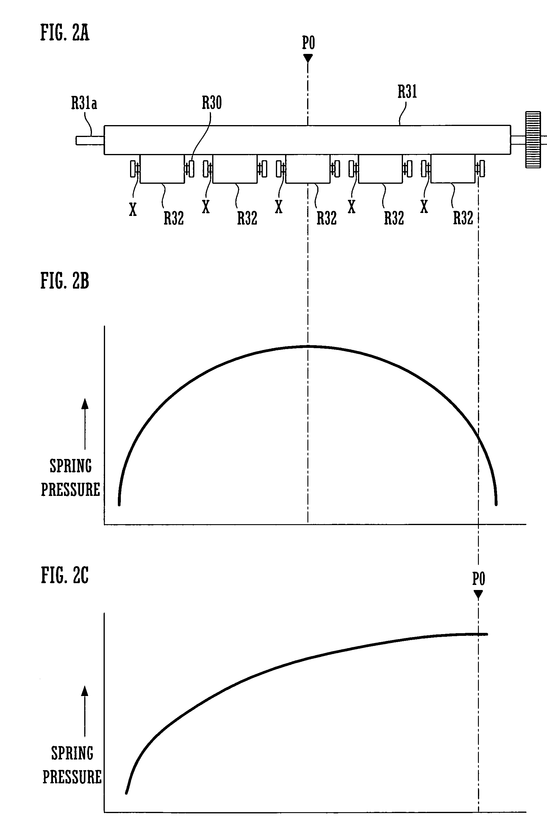
[0019] A sheet being transported is thus prevented from having creases thereon when the movable members are the driven rollers. The reference position is located in an approximately central part, or either one of opposite end portions, of the shaft of the rotation roller.

Problems solved by technology

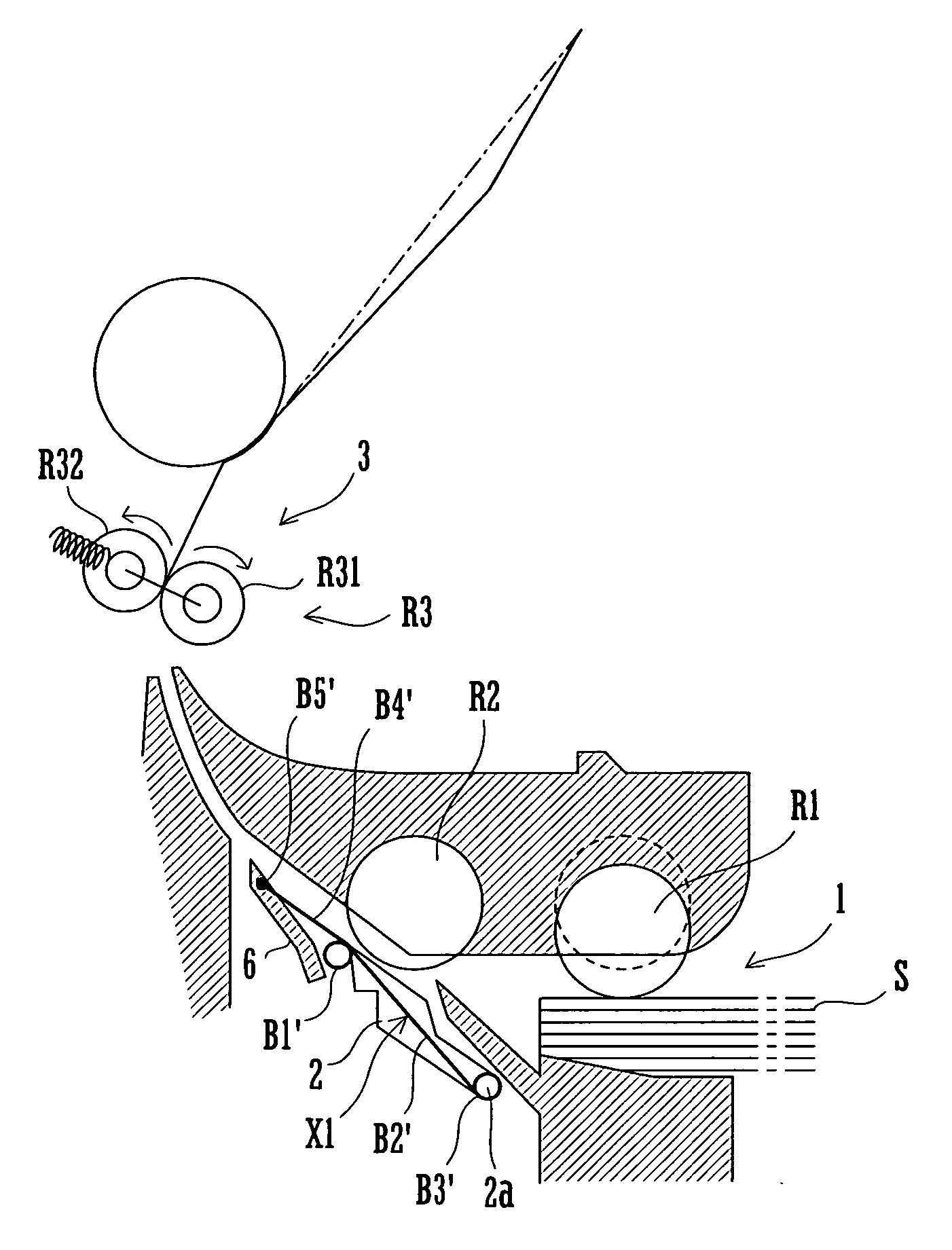
A resulting problem is that a sheet jam occurs with increased frequency because a sheet is more likely to collide with a movable member or with a rotation roller around a gap provided between the sheet transport guide and the movable member.
In FIG. 4, a sheet transport path has a particularly small radius of curvature around the gap 5 and, therefore, causes frequent occurrence of sheet jam.
However, the film member has difficulty in guiding a sheet along a sheet transport path which has a small radius of curvature.

Method used


Image

  • Sheet-conveying mechanism
  • Sheet-conveying mechanism
  • Sheet-conveying mechanism

Examples


Embodiment Construction

[0024] With reference to the accompanying drawings, several embodiments of the invention are described below.

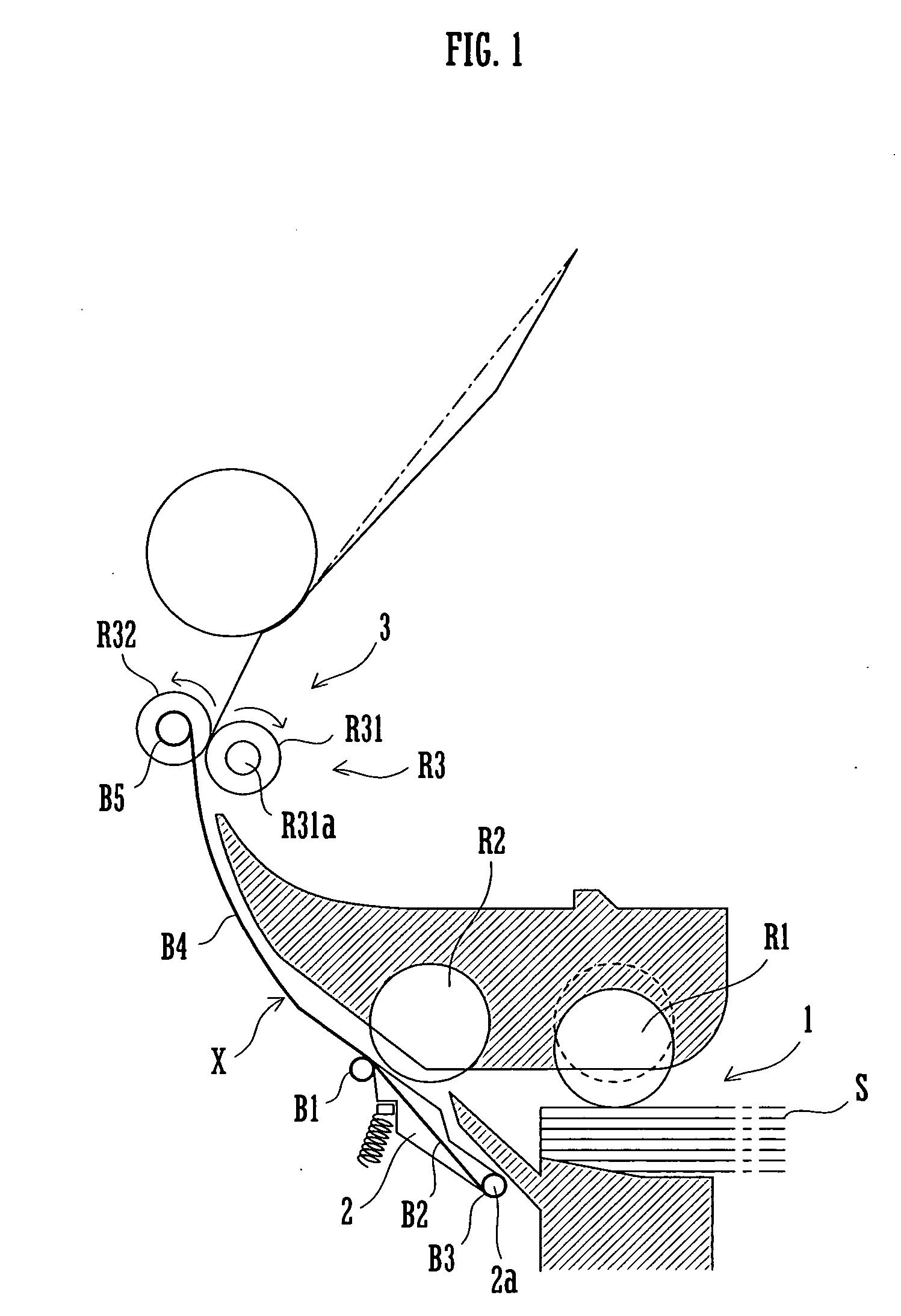
[0025]FIG. 1 is a schematic cross-sectional view of a sheet transport mechanism according to an embodiment of the invention. FIG. 2A is a schematic front view of the sheet transport mechanism. FIGS. 2B and 2C are graphs which show spring pressure distribution of a torsion coil spring.

[0026] The sheet transport mechanism is applied to a sheet feeding section of an image forming apparatus. The sheet transport mechanism includes a sheet transport guide X. The sheet transport guide X has a plurality of torsion coil springs X. The sheet transport guide X is arranged upstream of an idle roller pair R3 in a sheet transport direction. The idle roller pair R3 consists of an idle roller R31 and driven rollers R32. A sheet S, such as a sheet of record paper, is fed from a sheet feeding section 1 and transported by the idle roller pair R3 to a transfer section 3 where a toner image is ...


PUM


Abstract

A sheet transport guide includes a torsion coil spring (X). The spring (X) has a first arm (B4) with an end (B5). Through the end (B5), the spring (X) supports a rotation shaft of driven roller (R32) and applies elastic force to the roller (R32). Through the arm (B4) that is curved, the spring (X) guides a sheet toward a rotation roller R31. The spring (X) has a coil portion (B1) and an end (B3) of a second arm (B3) both fixed to a frame of an apparatus body. A plurality of driven rollers (R32) are aligned approximately parallel to a shaft (R31a) of the roller (R31). The rollers (R32) are each provided with the springs (X). A largest elastic force is applied to the roller (R32) at a predetermined reference position, and smaller elastic forces are applied to the other rollers (R32) at positions distant from the reference position.

Description

TECHNICAL FIELD [0001] The present invention relates to a sheet transport mechanism such as provided in image forming apparatuses, that includes a rotation roller, a movable member elastically biased toward the roller, and a sheet transport guide for guiding a sheet to be transported between the rotation roller and the movable member. BACKGROUND ART [0002] Conventional image forming apparatuses include a rotation roller for transporting a sheet such as of record paper, and a movable member such as a driven roller or a separation roller. The movable member is elastically biased toward the rotation roller. The rotation roller is rotated, thereby transporting a sheet as fed between the rotation roller and the movable member. Also, a sheet transport guide is provided upstream and / or downstream of the rotation roller in a sheet transport direction. The sheet transport guide guides a sheet between the rotation roller and the movable member. Or, the sheet transport guide guides a sheet whi...

Claims


Application Information

Patent Timeline
Patent Type & Authority Applications(United States)
IPC IPC(8): B65H3/52B65H3/66B65H5/06B65H5/38
CPCB65H3/5223B65H3/66B65H5/06B65H5/38
Inventor SEIKE, TOSHIHIKOKOHNO, AKIRAOHISHI, MASATSUGUHORI, TAKASHIIZUMI, HIDESHIJUJII, TOMOHIKO
Owner SHARP KK
Why Eureka
Eureka Blog
Learn More