Method to additively manufacture a fiber-reinforced ceramic matrix composite

a ceramic matrix and composite material technology, applied in the direction of additive manufacturing with solids, additive manufacturing apparatus, etc., can solve the problem of no reproducible and reliable manufacturing route, and achieve the effect of preventing rupture and/or stress

Active Publication Date: 2021-10-26
SIEMENS ENERGY GLOBAL GMBH & CO KG
View PDF20 Cites 0 Cited by
  • Summary
  • Abstract
  • Description
  • Claims
  • Application Information

AI Technical Summary

Benefits of technology

[0015]The method further comprises layer-by-layer building up or manufacturing the ceramic matrix material (base material) for the ceramic matrix composite by irradiating of a powder bed formed by the base material with an energy beam according to the desired and predetermined geometry of the component, wherein the base material is melted, solidified and thereby adhesively joined to the ceramic fiber. This is carried out in that (irradiating) parameters of the energy beam are advantageously locally chosen such that, in a contact region of the ceramic fiber and the powder bed, the ceramic fiber is only partly melted, and advantageously not completely melted. By the solely partial melting procedure, it is expediently achieved, that the ceramic fiber is not destroyed but its material is still intact and, at the same time adhesively joined to the solidified matrix material. In other words, the present invention pertains to the control of the irradiation process, such that the ceramic fiber can indeed be adhesively joined without losing its outstanding properties for the final CMC.
[0018]In an embodiment the fiber is brought or placed in the powder bed, particularly in the previously deposited layer of said powder bed, during the additive manufacture by a movable equipment or apparatus. This embodiment is advantageous, as it may allow for the exploitation of a greater design freedom during the additive manufacture. Said apparatus is, advantageously, movable independently from any further device hardware, such as an irradiation or scanning equipment. Said apparatus shall, advantageously, further be embodied in a very compact way, e.g. with outer extensions of only a few millimeters- or centimeters, such that any placement allows a lot of design freedom with regard to in-situ fiber placement in a layer of powdery base material along with an irradiation solidification step.
[0026]By means of these embodiments, it may be achieved that—even though the materials of the fiber and the base material (matrix material) are similar or the same—the material of the fiber may not be harmed during irradiation, but only particles may be melted due to size-dependent or melting point reductions. It is known, that a decrease of a spatial dimension of material below a defined threshold can reduce its melting point.
[0031]In an embodiment, the power or power density of the energy beam is reduced at a transition from the powder bed region to the contact region, advantageously such that—due to said reduction—the fiber is not completely melted, as compared to the base material for the ceramic matrix.
[0035]In an embodiment, the powder bed is preheated to temperatures of above 1500° C., particularly above 2000° C., for the prevention of rupture and / or stresses, e.g. by means of a laser, such as a CO2- or Nd:YAG-laser, an electron beam, or inductive heating means.

Problems solved by technology

A drawback to overcome in this context is particularly that the melting point of both materials of the same sort—i.e. matrix powder on the one side and a solid fiber on the other side—is approximately the same.
Up to now, there is no reproducible and reliable manufacturing route, except the “conventional” approaches which produce fibers / fabrics and a usually comprise a subsequent lamination or sintering step including post-infiltration.

Method used


Image

  • Method to additively manufacture a fiber-reinforced ceramic matrix composite
  • Method to additively manufacture a fiber-reinforced ceramic matrix composite

Examples


Embodiment Construction

[0049]Like elements, elements of the same kind and identically acting elements may be provided with the same reference numerals in the Figures.

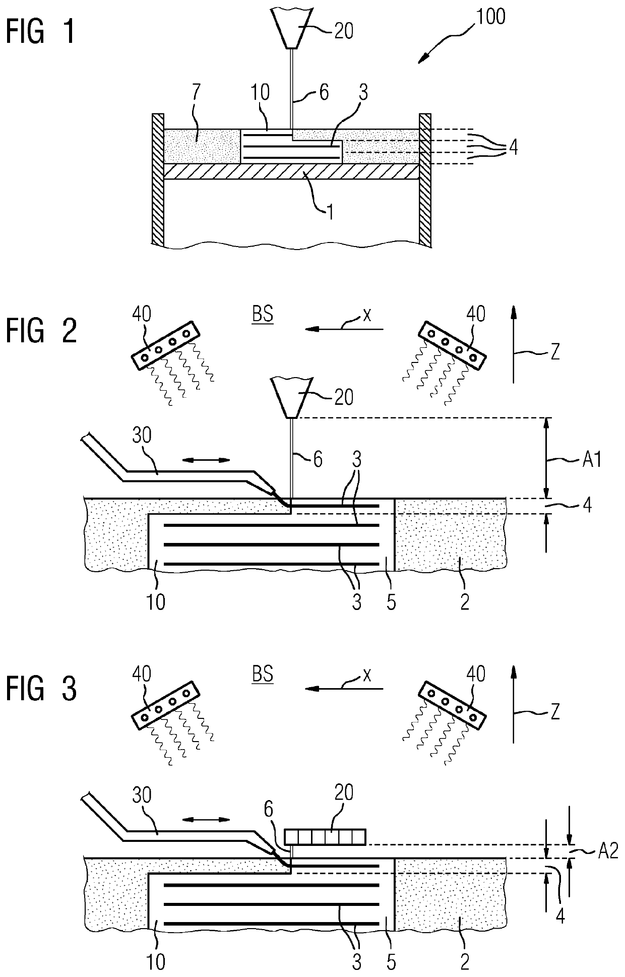
[0050]FIG. 1 indicates schematically a powder bed process for additively manufacturing a component 10. The process may be carried out in an additive manufacturing device 100. The process may further relate to selective laser melting, selective laser sintering and / or electron beam melting, for example.

[0051]The component is, advantageously, a turbo machine component, particularly applied in the flow path hardware of gas turbines.

[0052]It is commonly known in SLM processes that the component 10 is manufactured on top of a substrate or build platform 1. Particularly, the first layer to be manufactured of a metal component is adhesively joined or metallurgically bonded to the substrate 1. The component 10 may be depicted in a partially manufactured state. The component 10 is further built layer-by-layer out of the powder bed formed by a powdery b...


PUM

PropertyMeasurementUnit
temperaturesaaaaaaaaaa
bending strengthaaaaaaaaaa

Abstract

A method of additively manufacturing a ceramic matrix composite material includes providing a ceramic fiber and a powdery base material for a ceramic matrix composite and layer-by-layer building up the ceramic matrix material for the ceramic matrix composite by irradiating of a powder bed formed by the base material with an energy beam according to a predetermined geometry, wherein the base material is melted, solidified and adhesively joined to the ceramic fiber in that parameters of the energy beam are locally chosen such that in the contact region of the ceramic fiber and the powder bed, the ceramic fiber is only partly melted.

Description

CROSS REFERENCE TO RELATED APPLICATIONS[0001]This application is the US National Stage of International Application No. PCT / EP2018 / 050012 filed Jan. 2, 2018, and claims the benefit thereof. The International Application claims the benefit of European Application No. EP17153083 filed Jan. 25, 2017. All of the applications are incorporated by reference herein in their entirety.FIELD OF INVENTION[0002]The present invention relates to the additive manufacture of a ceramic matrix composite material, such as a fiber-reinforced material or, as the case may be, a component made thereof. Further, an apparatus and an according component are described.[0003]Preferably, the component denotes a component applied in a turbo machine, e.g. in the hot gas flow path hardware of a gas turbine. The component is, thus, advantageously made of a superalloy or nickel-based alloy, particularly a precipitation hardened alloy.BACKGROUND OF INVENTION[0004]Additive manufacturing techniques comprise e.g. powder ...

Claims


Application Information

Patent Timeline
Patent Type & Authority Patents(United States)
IPC IPC(8): C04B35/83C04B35/628C04B35/657C04B35/117C04B35/185B33Y10/00B33Y30/00B33Y80/00B28B1/00C04B35/488C04B35/565C04B35/80
CPCC04B35/83B28B1/001B33Y10/00B33Y30/00B33Y80/00C04B35/117C04B35/185C04B35/488C04B35/565C04B35/62852C04B35/62857C04B35/62863C04B35/62873C04B35/657C04B35/80C04B2235/3217C04B2235/3244C04B2235/3463C04B2235/3826C04B2235/428C04B2235/5224C04B2235/5228C04B2235/5236C04B2235/5244C04B2235/5248C04B2235/6026C04B2235/616C04B2235/667C04B35/62847C04B35/653C04B2235/5264C04B2235/5268C04B2235/5436C04B2235/665C04B2235/77C04B2235/96C04B2235/963B33Y70/00B29C64/153B29C64/165Y02P10/25C04B35/52
Inventor BRANDT, MILANDIETRICH, JENSKELBASSA, INGOMAR
Owner SIEMENS ENERGY GLOBAL GMBH & CO KG
Why Eureka
Try Eureka