
Anomaly detection apparatus, anomaly detection method, and computer-readable recording medium

a technology of anomaly detection and anomaly detection, applied in the field of anomaly detection apparatus, can solve the problems of difficult alignment, inability to enhance alignment accuracy, and difficulty in using the alignment disclosed in patent document 1, and achieve the effect of high accuracy of anomaly detection

Active Publication Date: 2021-10-19
NEC CORP
View PDF8 Cites 0 Cited by
  • Summary
  • Abstract
  • Description
  • Claims
  • Application Information

AI Technical Summary

Benefits of technology

[0036]According to the invention as described above, highly accurate anomaly detection becomes possible, by simultaneously optimizing a parameter for image transformation suitable for anomaly detection and a parameter for identifying whether an image that has undergone image transformation is anomalous or normal.

Problems solved by technology

Alignment is difficult in the case where these situations arise.
However, it is actually difficult to use the alignment that is disclosed in Patent Document 1 in combination with the alignment that is disclosed in Patent Document 2.
This is because the evaluation criteria of whether images coincide are different in both, and the alignment accuracy cannot be enhanced simply by using the features of both in combination.
On the other hand, with alignment that is based on edges, the transformation parameter cannot be derived with a solution that solves a simultaneous equation.
In this way, the alignment that is disclosed in Patent Document 1 and the alignment that is disclosed in Patent Document 2 employ completely different methods of estimating the transformation parameter, and it is difficult to extend these techniques to perform alignment that uses both feature points and edges.

Method used


Image

  • Anomaly detection apparatus, anomaly detection method, and computer-readable recording medium
  • Anomaly detection apparatus, anomaly detection method, and computer-readable recording medium
  • Anomaly detection apparatus, anomaly detection method, and computer-readable recording medium

Examples


first example embodiment

[0048]Hereinafter, an anomaly detection apparatus, an anomaly detection method and a program according to a first example embodiment of the invention will be described, with reference to FIGS. 1 to 8.

Apparatus Configuration

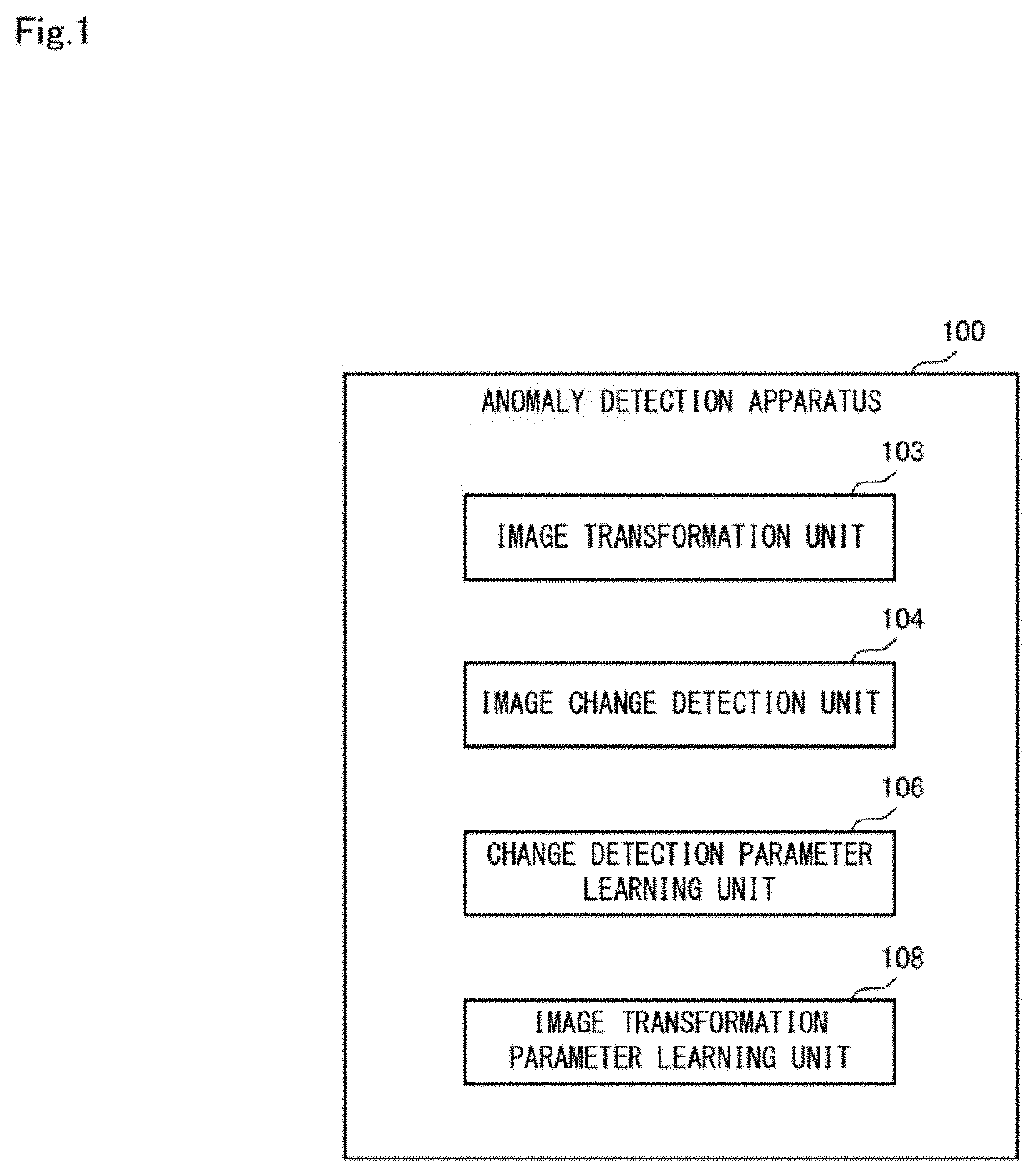
[0049]Initially, a configuration of the anomaly detection apparatus according to the first example embodiment will be described using FIG. 1. FIG. 1 is a block diagram showing a schematic configuration of the anomaly detection apparatus according to the first example embodiment of the invention.

[0050]An anomaly detection apparatus 100 according to the first example embodiment shown in FIG. 1 is for detecting anomalies in an inspection object, using an inspection image in which the inspection object appears and a reference image showing a normal state of the inspection object. As shown in FIG. 1, the anomaly detection apparatus 100 is provided with an image transformation unit 103, an image change detection unit 104, a change detection parameter learning unit 106, ...

second example embodiment

[0111]Next, an anomaly detection apparatus, an anomaly detection method and a program according to a second example embodiment of the invention will be described, with reference to FIGS. 9 and 10.

[0112][Apparatus Configuration]

[0113]Initially, a configuration of the anomaly detection apparatus according to the second example embodiment will be described using FIG. 9. FIG. 9 is a block diagram showing a specific configuration of the anomaly detection apparatus according to the second example embodiment of the invention.

[0114]In the abovementioned first example embodiment, only a label image indicating a correct answer value of an anomalous region in the coordinate system of the reference image is used as a training image for learning, whereas, in the second example embodiment, an ideally transformed inspection image is, furthermore, also used.

[0115]Thus, as shown in FIG. 9, an anomaly detection apparatus 200 according to the second example embodiment is provided with an ideally trans...


PUM


Abstract

An anomaly detection apparatus 100 includes an image transformation unit 103 that calculates an image transformation parameter, based on an inspection image in which an inspection object appears, a reference image indicating a normal state of the inspection object and a parameter for image transformation parameter calculation, and performs image transformation on the inspection image using the image transformation parameter, an image change detection unit 104 that collates the reference image and the image-transformed inspection image using a change detection parameter, and calculates an anomaly certainty factor indicating whether there is a change in a specific region of the inspection image, a change detection parameter learning unit 106 that learns the change detection parameter, based on a difference between a training image indicating a correct answer value of the change and the anomaly certainty factor, and an image transformation parameter learning unit 108 that learns the parameter for image transformation parameter calculation, based on a collection amount derived from the difference between the training image and the anomaly certainty factor and to be applied to the inspection image that has undergone image transformation.

Description

CROSS REFERENCE TO RELATED APPLICATIONS[0001]This application is a National Stage of International Application No. PCT / JP2017 / 035746 filed Sep. 29, 2017, the disclosure of which is incorporated herein in its entirety by reference.TECHNICAL FIELD[0002]The present invention relates to an anomaly detection apparatus and au anomaly detection method that are for detecting anomalies in an object by collating a reference image and an inspection image that are shot of the object, and furthermore relates to a computer-readable recording medium that includes a program recorded thereon for realizing the apparatus and method.BACKGROUND ART[0003]Heretofore, apparatuses whose object is to automatically detect anomalies that are evident from the outward appearance of industrial components, infrastructural structures and the like using images have been proposed. Such apparatuses map a reference image shot of the object in a normal state and an inspection image shot of the object at the time of insp...

Claims


Application Information

Patent Timeline
Patent Type & Authority Patents(United States)
IPC IPC(8): G06K9/46G06T7/00
CPCG06T7/001G06T2207/20081G06T2207/30148G01N21/88G06T7/33
Inventor TAKAHASHI, KATSUHIKONAKATANI, YUICHI
Owner NEC CORP
Learn More