Lawn mower

a mower and blade technology, applied in the field of lawn mowers, can solve the problems of affecting the mowing operation, and the bottom disk as a guard member, which is commonly made of a thin metal plate, with thin, long prong portions on the periphery, and is easily deformed or damaged, so as to achieve the desired durability and facilitate the mowing operation

Active Publication Date: 2021-09-28
YAMABIKO CORP
View PDF12 Cites 0 Cited by
  • Summary
  • Abstract
  • Description
  • Claims
  • Application Information

AI Technical Summary

Benefits of technology

[0010]On the fields to be mowed by lawn mowers, obstructions to the mowing operation may be present, such as stones and rocks as well as objects to be protected left on the ground, e.g., golf balls. If the lawn mower described in EP 1211924 A1, which inevitably has a large mass, bumps against hard obstructions on the field, such as stones and rocks, a huge impact is applied to the bottom disk. In such occasions, the bottom disk as a guard member, commonly made of a thin metal plate, with thin, long prong portions provided on its periphery, is easily deformed or damaged.
[0012]To address such issues, measures to secure the strength of the bottom disk for improved durability may be considered by thickening the bottom disk or employing a rigid material therefor. However, such measures may lead to a weight increase, causing various problems, such as an increase in the load on the operating motor to which the bottom disk is attached, a reduced operable time, inconvenience in carrying, and a far greater impact applied to the bottom disk.
[0013]The present disclosure has been made in view of the foregoing, and provides a lawn mower capable of securing desired durability as well as suppressing the weight increase.
[0020]In some embodiments, the cutting disk is supported such that it is movable upward relative to the body chassis of the lawn mower so as to ascend and descend relative to the body chassis of the lawn mower, thereby adjusting the height of mowing operation to be performed by the mowing blade.
[0022]According to the present disclosure, when the prong portions on the periphery of the bottom disk are elastically deformed inward due to an external force applied thereto, the prong portions abut the cutting disk so as to transfer the received external force to the cutting disk (in other words, the external force is partially received by the cutting disk), and the displacement of the prong portions is restricted by the presence of the cutting disk. Thus, even when the bottom disk is formed thin and light, the strength thereof can be easily secured. Therefore, the prong portions of the bottom disk are less likely to be deformed or damaged, even when they bump against hard obstructions on the ground within the mowing area. As a result, desired durability can be secured.

Problems solved by technology

On the fields to be mowed by lawn mowers, obstructions to the mowing operation may be present, such as stones and rocks as well as objects to be protected left on the ground, e.g., golf balls.
In such occasions, the bottom disk as a guard member, commonly made of a thin metal plate, with thin, long prong portions provided on its periphery, is easily deformed or damaged.
If the bottom disk, in particular, the prong portions provided on the periphery of the bottom disk are deformed or damaged as described above, the mowing blade of the cutting disk is exposed, thereby possibly damaging itself as well as golf balls on the field.
However, such measures may lead to a weight increase, causing various problems, such as an increase in the load on the operating motor to which the bottom disk is attached, a reduced operable time, inconvenience in carrying, and a far greater impact applied to the bottom disk.

Method used


Image

  • Lawn mower
  • Lawn mower
  • Lawn mower

Examples


Embodiment Construction

[0032]An embodiment of the present disclosure will be described below with reference to the drawings.

[Overall configuration of lawn mower 1]

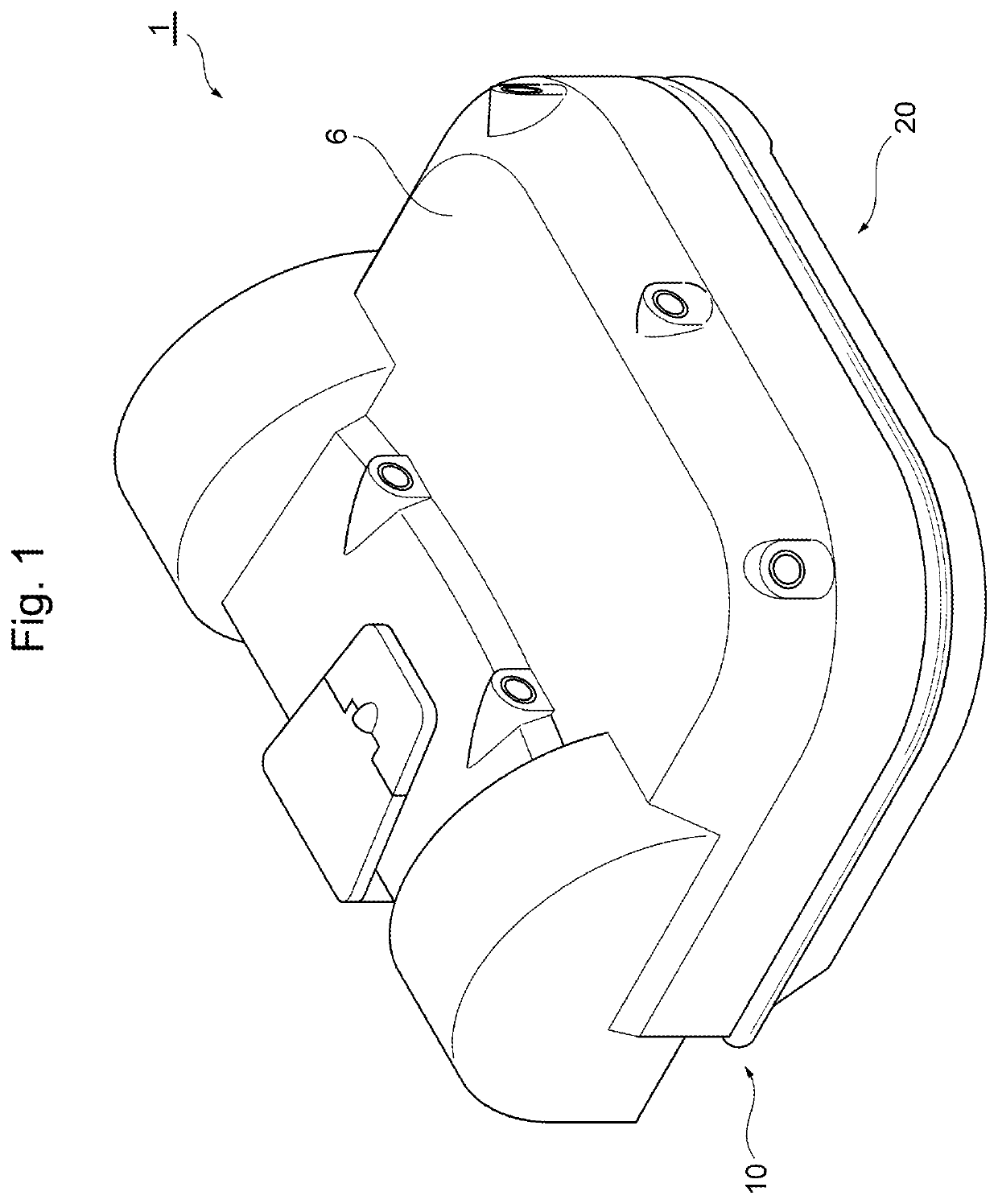
[0033]FIG. 1 is an overall perspective view of an embodiment of a lawn mower according to the present disclosure. FIG. 2 is an exploded perspective view of the lawn mower illustrated in FIG. 1 when a body housing is removed from the lawn mower.

[0034]A lawn mower 1 of the embodiment shown in the drawings is an unmanned automatically traveling lawn mower (a so-called robotic lawn mower or robotic mower) that is configured to travel automatically while mowing grass within a predetermined mowing area (field).

[0035]The lawn mower 1 mainly includes a traveling unit 10 adapted to drive the wheels for automatic traveling, an operating unit 20 adapted to drive a mowing blade to perform mowing operation, a control unit (not shown) adapted to automatically control the traveling unit 10 (or a traveling motor thereof) and the operating unit 20 (or an operati...


PUM


Abstract

A lawn mower capable of securing desired durability as well as suppressing a weight increase is provided. When prong portions on the periphery of a bottom disk are elastically deformed inward due to an external force applied thereto, the prong portions abut a cutting disk, so that the received external force is transferred to the cutting disk (that is, the external force is partially received by the cutting disk), and the displacement of the prong portions is restricted by the presence of the cutting disk.

Description

RELATED APPLICATIONS[0001]The present application claims priority from Japanese patent application JP 2018-097986 filed on May 22, 2018, the content of which is hereby incorporated by reference into this application.BACKGROUND OF THE INVENTION1. Field of the Invention[0002]The present disclosure relates to a lawn mower, in particular, the one adapted to protect objects left on the ground from its mowing blade.2. Description of the Related Art[0003]In recent years, automatically traveling lawn mowers (also referred to as autonomously traveling or self-traveling lawn mowers) for mowing lawns or weeds on the ground (hereinafter also collectively referred to as grass) without the need of operations by operators have come into widespread use. Such automatically traveling lawn mowers include, for example, electric motors for driving wheels (hereinafter referred to as a traveling motor) and for driving mowing blades (or cutting blades) (hereinafter referred to as an operating motor), a con...

Claims


Application Information

Patent Timeline
Patent Type & Authority Patents(United States)
IPC IPC(8): A01D34/74A01D34/73A01D34/78A01D101/00
CPCA01D34/74A01D34/733A01D34/736A01D34/78A01D2101/00G05D2201/0208A01D34/828
Inventor FUSE, YOICHIYAMADA, RYOTA
Owner YAMABIKO CORP
Why Eureka
Try Eureka