Method of introducing prestress to beam-column joint in triaxial compression

a beamcolumn joint and beamcolumn joint technology, applied in the direction of joists, girders, shock-proofing, etc., can solve the problems of fatal shear fractures of the entire structure, brittle fractures without toughness, etc., to prevent diagonal cracks, reasonable and cost-effective designs, and prevent the effect of undue compressive stress intensity

Active Publication Date: 2021-09-07
KUROSAWA CONSTR CO LTD
View PDF17 Cites 1 Cited by
  • Summary
  • Abstract
  • Description
  • Claims
  • Application Information

AI Technical Summary

Benefits of technology

[0030](1) As above, prestresses are introduced in three axial directions in a ratio specified by equation (1), where the prestress introduced in the columns is decreased taking into consideration variations in the axial force acting on the columns. This makes the ratio of the compressive stress intensities acting on the beam-column joint in three axial directions substantially equal to 1:1:1. The compressive stress intensities of this ratio generate a resultant compressive stress on a diagonal of the beam-column joint at an ideal angle of 45 degrees approximately. This compressive stress can completely or nearly completely cancel a diagonal tensile force that will be generated on a diagonal of the beam-column joint by an input shear force acting on the beam-column joint by a seismic load, thereby preventing diagonal cracks leading to shear failure from occurring with reliability. Moreover, since the prestress introduced in the columns is lower than the prestress introduced in the beams, the axial force acting on the columns is controlled within an allowable stress intensity range even under the stationary load (vertical load). This prevents the compressive stress intensity from becoming unduly high.
[0031](2) The values of σxand σy mentioned in equation (1) may by limited within the range between 2.0 and 10.0 N / mm2. Then, the value of σz is limited within the range between 0.6 and 9.0 N / mm2 according to the ratio specified by equation (1). The above ranges are set based on the design standard strength Fc of concretes that are commonly used in PC structures (Fc=40N / mm2−60N / mm2). This does not require excessively low or excessively high stress introducing forces and allows reasonable and cost-effective designs.
[0032](3) While the axial force acting on columns varies depending on the floor level or the location in a horizontal plane, the prestress introduced in the columns in at least five layers (or stories) of a building may be uniformized. This allows the differences in the axial forces acting on the columns in the five layers to be adjusted by the range of ratio according to equation (1) (σz=0.3−0.9) to control the axial forces acting on the columns within an allowable range. This allows efficient designs and constructions and eliminates errors in tensioning during construction.
[0033](4) There may be cases where a diagonal tensile force generated in a beam-column joint by an extremely great earthquake is partly cancelled by the prestress introduced therein and partly remains. If the prestress is introduced such that a tensile stress intensity resulting from the diagonal tensile force will not exceed the allowable tensile stress intensity of the concrete used to construct the beam-column joint even in such cases, diagonal shear cracks fatal to the building structure will not occur. This ensures aseismatic performance of the building.
[0034](5) The method of introducing prestress according to the present invention is based on a principle that is completely different from conventional RC structures, in which reinforcing bars are provided in a beam-column joint in order to reactively prevent development of cracks after they occur. The method of introducing prestress according to the present invention brings a beam-column joint in triaxial compression with a most reasonable balance that is set taking into consideration factors leading to variations in the axial forces acting on the columns. This proactively cancels tensile forces that may cause cracks to reliably prevent cracks from occurring.

Problems solved by technology

Such cracks of the concrete members thus damaged develop further to cause brittle fractures without toughness.
Such breaking of the beam-column joint directly leads to collapse of the structural frame, eventually resulting in fatal shear fractures of the entire structure.

Method used


Image

  • Method of introducing prestress to beam-column joint in triaxial compression
  • Method of introducing prestress to beam-column joint in triaxial compression
  • Method of introducing prestress to beam-column joint in triaxial compression

Examples


Embodiment Construction

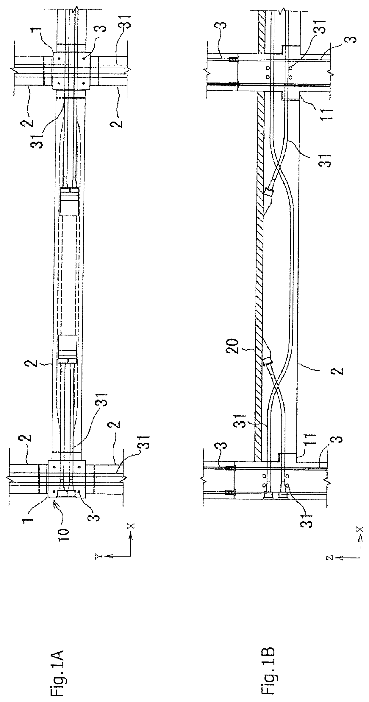
[0040]FIGS. 1A and 1B show a portion of a building to which the present invention is applied. FIGS. 1A and 1B are, respectively, a plan view and a side view of beam-column joints in a middle floor of a multi-story building.

[0041]PC columns 1 and PC beams 2 in the structure shown in FIGS. 1A and 1B are precast members. The PC columns 1 are set upright on the foundation (not shown). Prestressing steel rods 3 serving as prestressing tendons are passed through the PC column 1 and tensionally anchored (in other words, fixed in a tensioned state). The PC beams 2 are set on corbels 11 provided on the PC columns 1. Prestressing cables 31 provided in the PC beams 2 serving as prestressing tendons are passed through the beam-column joints and tensionally anchored.

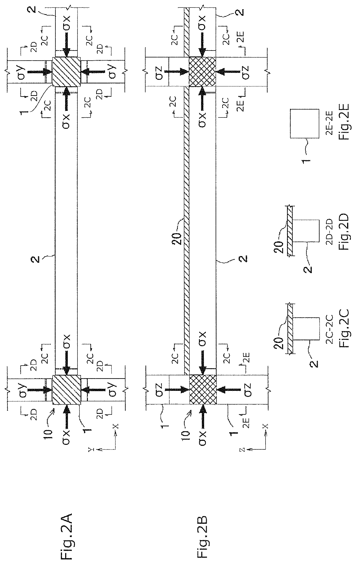
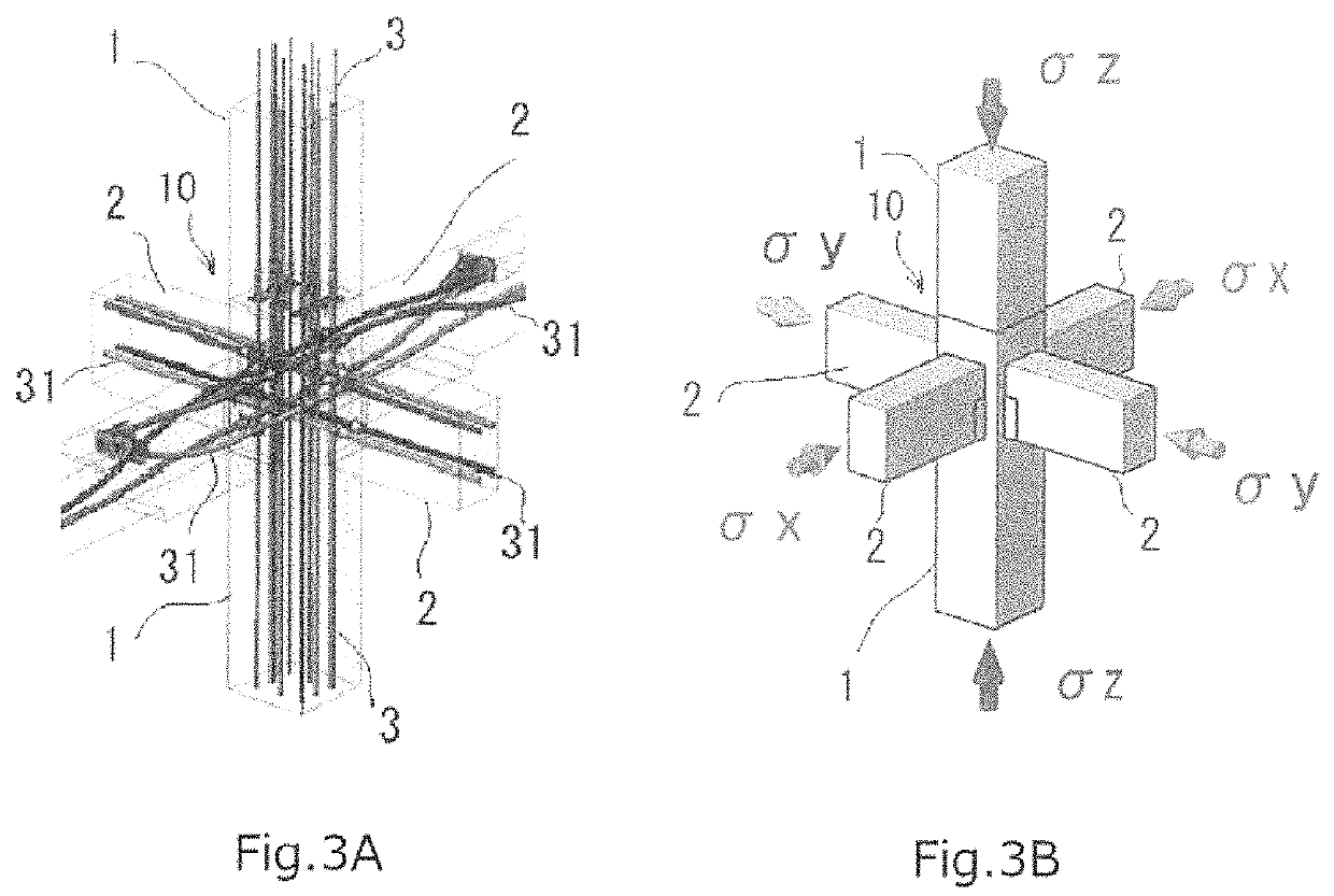
[0042]As shown in FIGS. 1A and 1B, the prestressing steel rods 3 and the prestressing cables 31 serving as prestressing tendons are passed through the beam-column joint in two horizontal directions (X, Y) and the vertical direction (...


PUM


Abstract

There is provided a method of prestressing a beam-column joint with an appropriate ratio among the magnitudes of compression in the directions of X, Y, and Z axes. The method introduces prestress in a beam-column joint with a tensile introducing force generated by tensionally anchoring prestressing tendons that are arranged in PC beams extending along two horizontal directions (or X axis and Y axis) and PC columns extending along the vertical direction (or Z axis) and passed through the beam-column joint to bring the beam-column joint in triaxial compression, the prestress being introduced such that a diagonal tensile force T generated by an input shear force due to a seismic load of an extremely great earthquake that may occur very rarely will be cancelled completely or partially so as not to allow diagonal cracks to occur. The ratio of the prestresses introduced in the directions of the respective axes satisfies the following equation (1):σx:σy:σz=1:1:0.3−0.9  (1)where σx, σy, and σz are prestresses introduced in the directions of the X axis, the Y axis, and the Z axis respectively.

Description

[0001]Priority is claimed on Japanese Patent Application No. 2019-167793 filed on Sep. 13, 2019, the content of which is incorporated herein by reference.TECHNICAL FIELD[0002]The present invention relates to a method of introducing prestress into a beam-column joint (or column-beam joint) of a prestressed concrete structure (PC structure) to establish triaxial compression.BACKGROUND ART[0003]It is demonstrated by many studies in the past that a beam-column joint formed by concrete members extending in three axial directions (i.e. beams extending in two horizontal directions x and y and columns extending in the vertical direction z) may develop diagonal shear cracks caused by a diagonal tensile force. Such cracks of the concrete members thus damaged develop further to cause brittle fractures without toughness. Such breaking of the beam-column joint directly leads to collapse of the structural frame, eventually resulting in fatal shear fractures of the entire structure.[0004]Patent li...

Claims


Application Information

Patent Timeline
Patent Type & Authority Patents(United States)
IPC IPC(8): E04B1/22E04B1/98E04H9/02E04C3/34
CPCE04B1/22E04B1/98E04C3/34E04H9/021E04H9/025E04C3/293E04C3/26E04C5/12E04C5/10
Inventor KUROSAWA, RYOHEI
Owner KUROSAWA CONSTR CO LTD
Why Eureka
Try Eureka