
Snapping of denture teeth

a denture tooth and tooth technology, applied in the field of denture teeth, can solve the problems of inconvenient denture tooth shape change, inconvenient denture tooth design, and inability to achieve the effect of facilitating the method

Active Publication Date: 2021-08-10
3SHAPE AS
View PDF10 Cites 0 Cited by
  • Summary
  • Abstract
  • Description
  • Claims
  • Application Information

AI Technical Summary

Benefits of technology

The patent describes a method for designing dentures for patients who have no teeth or are still wearing some of their own teeth. The method uses a virtual design environment that allows dental technicians to place denture teeth in a patient's mouth and ensure that they meet certain distances from each other. This helps achieve a natural-looking and functional denture design. The virtual environment also provides tools to customize specific functions of the denture design and improve its overall appearance.

Problems solved by technology

It remains a problem to improve the virtual designing of the denture.
However, designing a denture one tooth at a time takes considerable time and even when doing so a tooth transformation may undesirably affect a previous tooth transformation.
This may lead to situation where the users attempts to transform a denture tooth in a particular way but is prevented in doing so since the enforcement of the design rule will prevent and override the transformation.
Thus the term transforming is not used to describe modeling, morphing, change of shape, form, size etc. of a denture tooth, since the denture teeth will typically be pre-manufactured and thus changing the shape of the individual denture teeth may not be advantageous.
The anterior teeth distance may be maintained by only looking in distal direction starting from the tooth that the user has started to operate on, resulting in controllable gaps.

Method used


Image

  • Snapping of denture teeth
  • Snapping of denture teeth
  • Snapping of denture teeth

Examples


embodiment 1

[0174]2. A method , wherein the at least one design rule is selected from a group of independent design rules comprising:[0175]maintain occlusion with antagonist teeth in the block,[0176]maintain interproximal contact with neighboring teeth in the block.

[0177]3. A method according to embodiment 1 or 2, wherein the at least one design rule is selected from a group of dependent design rules comprising:[0178]maintain distance between at least one tooth from one block and at least one tooth from another block,[0179]maintain relative position of at least one tooth from one block with respect to a reference plane or reference line and the relative position of at least one tooth from another block with respect to the reference plane or reference line.

embodiment 3

[0180]4. A method , wherein the reference plane is the midplane or midline.

[0181]5. A method according to any one of the embodiments 1-4, wherein the denture teeth are grouped in four blocks, comprising according to the ISO 3950 standard (FDI): an upper anterior block comprising teeth 13, 12, 11, 21, 22, 23;[0182]a lower anterior block comprising teeth 43, 42, 41, 31, 32, 33;[0183]a left posterior block comprising at least teeth 24, 25, 26, 27, 34, 35, 36, 37; and[0184]a right posterior block comprising at least teeth 14, 15, 16, 17, 44, 45, 46, 47.

embodiment 5

[0185]6. A method , wherein the upper anterior block is placed first, the left and right posterior blocks are placed second and the lower anterior block is placed third.

[0186]7. The method according to any one or more of the previous embodiments, wherein the pre-setup occlusion is maintained regardless of the transformations performed by the user.

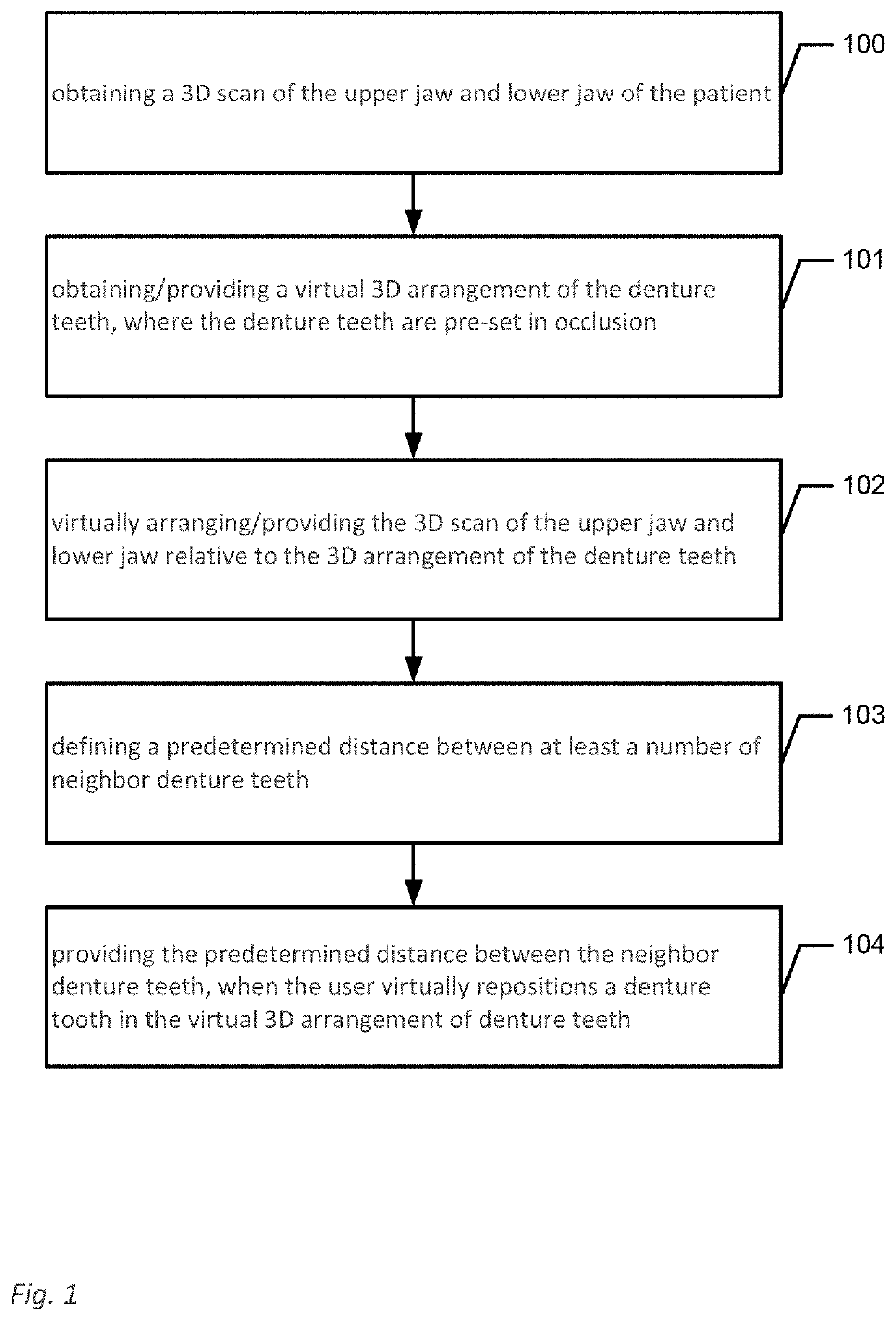
[0187]8. A method according to any one of the embodiments 1-7, wherein the method further comprises:[0188]defining a predetermined distance between at least a number of neighbor denture teeth;[0189]providing the predetermined distance between the neighbor denture teeth, when the user digitally repositions a denture tooth in the virtual 3D arrangement of denture teeth.

[0190]9. A method for digitally designing a denture for a patient, where the denture comprises a plurality of denture teeth, where designing the denture comprises transforming, such as relocating, repositioning and / or rotating, denture teeth of the denture, wherein the method c...


PUM


Abstract

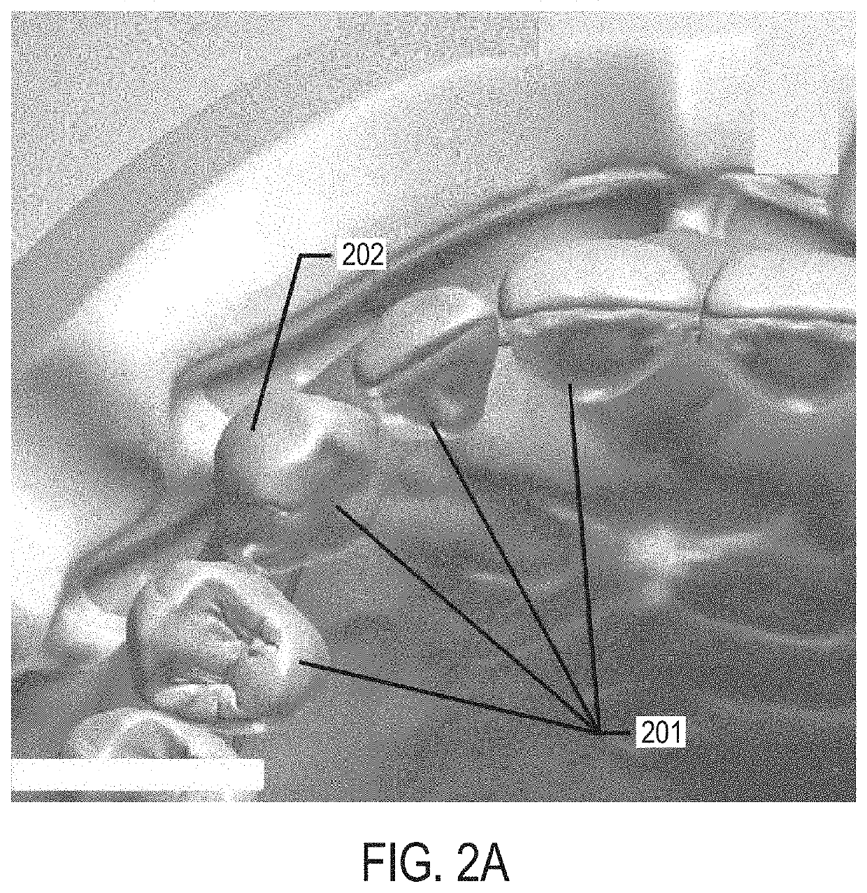
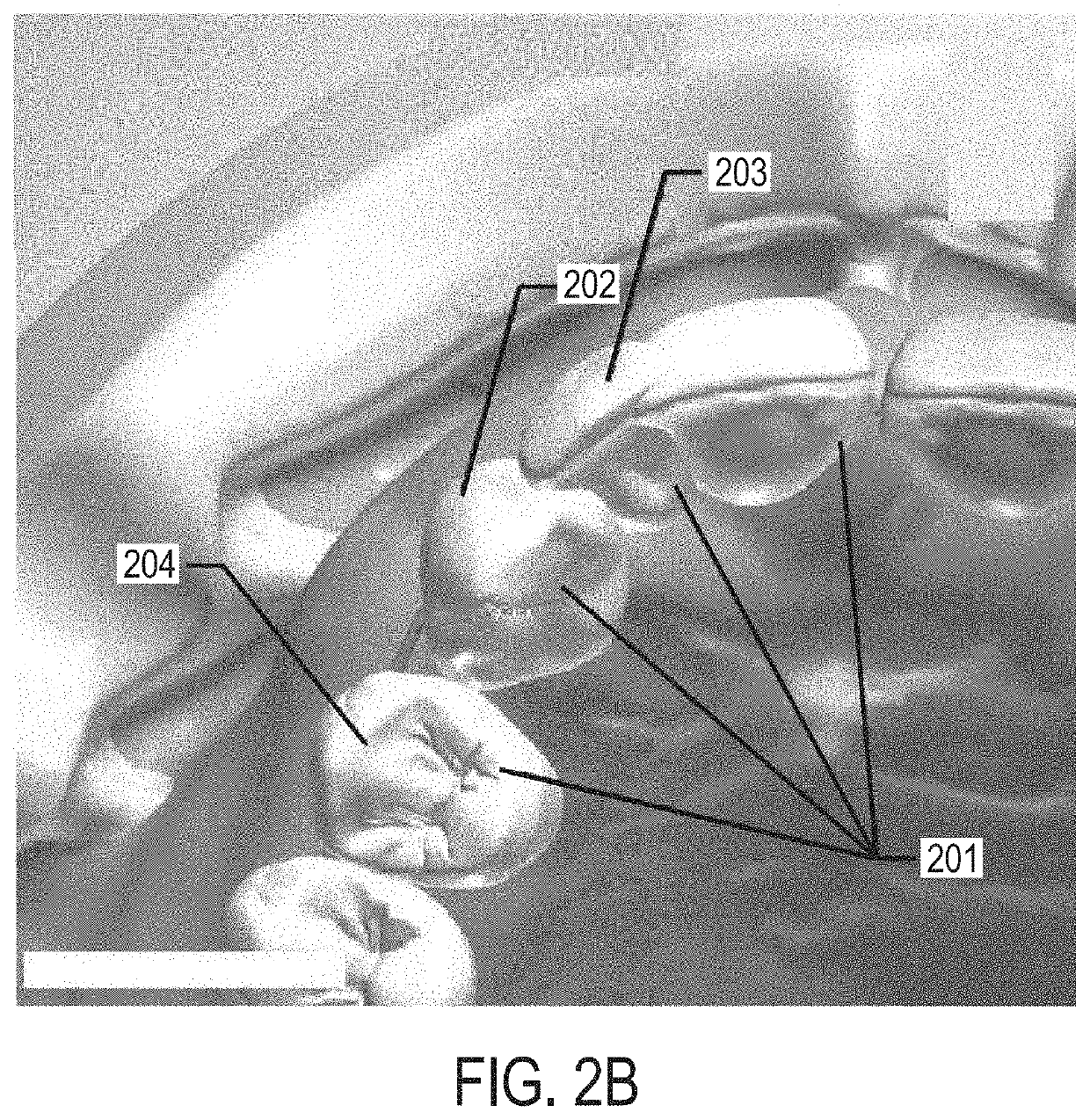
A method for digitally designing a denture for a patient, where the denture includes a plurality of denture teeth, where designing the denture includes transforming the denture, and where the denture teeth are grouped in at least two blocks where each block includes at least two denture teeth. The method includes obtaining a 3D scan of the upper jaw and lower jaw of the patient; obtaining a digital 3D arrangement of the denture teeth, where the denture teeth are pre-set in occlusion; digitally arranging the 3D scan of the upper jaw and lower jaw relative to the 3D arrangement of the denture teeth; and digitally transforming at least one denture tooth based on input from a user; where at least one design rule is enforced that affect one or more, but not all of the blocks, when the at least one denture tooth is transformed.

Description

FIELD OF THE INVENTION[0001]This invention generally relates to a method, a system and a virtual environment for virtually / digitally designing a denture for a patient, where the denture comprises a plurality of denture teeth. More particularly, the invention relates to designing the denture by transforming, such as relocating, repositioning and / or rotating, denture teeth of the denture.BACKGROUND OF THE INVENTION[0002]3Shape's WO12041329A1 discloses is a method for modeling and manufacturing a denture for a patient, where the denture comprises a gingival part and artificial teeth, wherein the method comprises: providing a 3D scan comprising at least part of the patient's oral cavity; virtually modeling at least part of the denture using the 3D scan; obtaining virtual teeth to represent the artificial teeth; virtually modeling at least one of the virtual teeth to obtain a set of modeled virtual teeth; manufacturing the modeled virtual teeth in a first material; manufacturing the ging...

Claims


Application Information

Patent Timeline
Patent Type & Authority Patents(United States)
IPC IPC(8): A61C13/34A61C11/00A61C9/00A61C13/00
CPCA61C9/004A61C13/0004A61C13/34A61C11/00A61C13/01
Inventor FISKER, RUNE
Owner 3SHAPE AS
Learn More