Additive manufacturing

a technology of additive manufacturing and metallic components, applied in additive manufacturing, manufacturing tools, process efficiency improvement, etc., can solve the problems of affecting the quality of components, affecting the appearance of components, so as to improve the surface finish, reduce the surface roughness, and improve the effect of surface finish

Active Publication Date: 2021-07-13
SIEMENS ENERGY GLOBAL GMBH & CO KG
View PDF13 Cites 0 Cited by
  • Summary
  • Abstract
  • Description
  • Claims
  • Application Information

AI Technical Summary

Benefits of technology

[0026]The applicants have found that subjecting the component and support structure to a thermal pulse removes a surface layer and thereby reduces the strength of the interface (or may break at least some of the interface) between the support structure and component without having any notable adverse effect on the material properties of the component. In fact the thermal pulse may improve the fatigue properties of the component.
[0031]In contrast as the interface is formed of fine features they are subjected to a greater heat transfer. Without being bound by any particular theory it is, therefore, believed that the thermal pulse causes a localised (or selective) vaporisation, oxidation or melting of the interface features. Thus, the interface is weakened and in some parts may be broken and the support can be more easily removed.
[0039]The applicants have, surprisingly, found that the application of a further thermal pulse after removal of the support structure provides an improved surface finish by reducing surface roughness. For example, this may reduce surface roughness resulting from remnants of the support structure interface or surface roughness of downward facing surfaces (which those in the art will appreciate may typically exhibit a degree of inherent roughness as a result of unintended powder melting below the layer desired).

Problems solved by technology
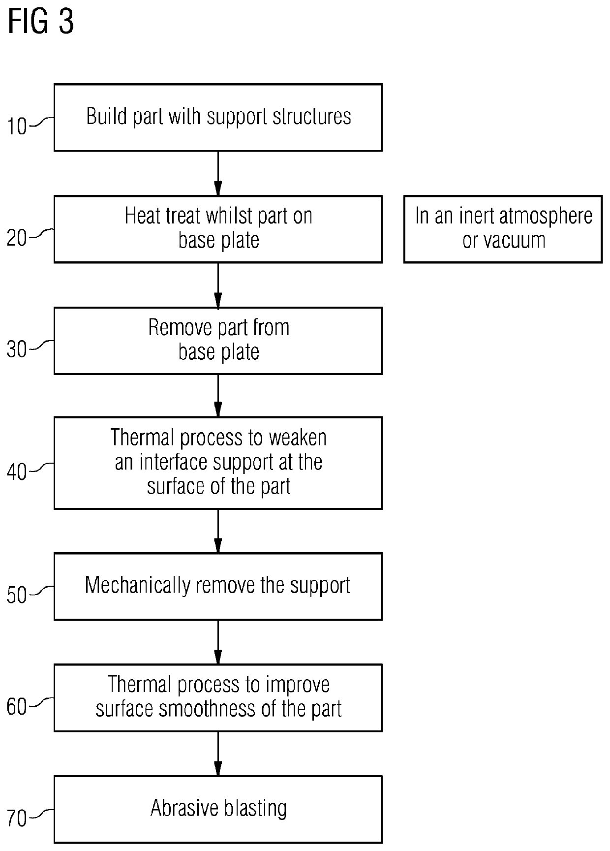
However, particularly for high performance metals (such as superalloys), the interface must be very strong and as a result the supports structure is difficult to remove.
Sharp cutting tools are used with considerable force and there is a danger that the surface of component may be damaged during this removal process.
However, such supports generally are of no practical use for geometries larger than dental copings and crowns.
Supports that are easy to remove conventionally do not provide sufficient strength to withstand the stresses placed on them by the selective laser melting process.

Method used


Image

  • Additive manufacturing
  • Additive manufacturing
  • Additive manufacturing

Examples


Embodiment Construction

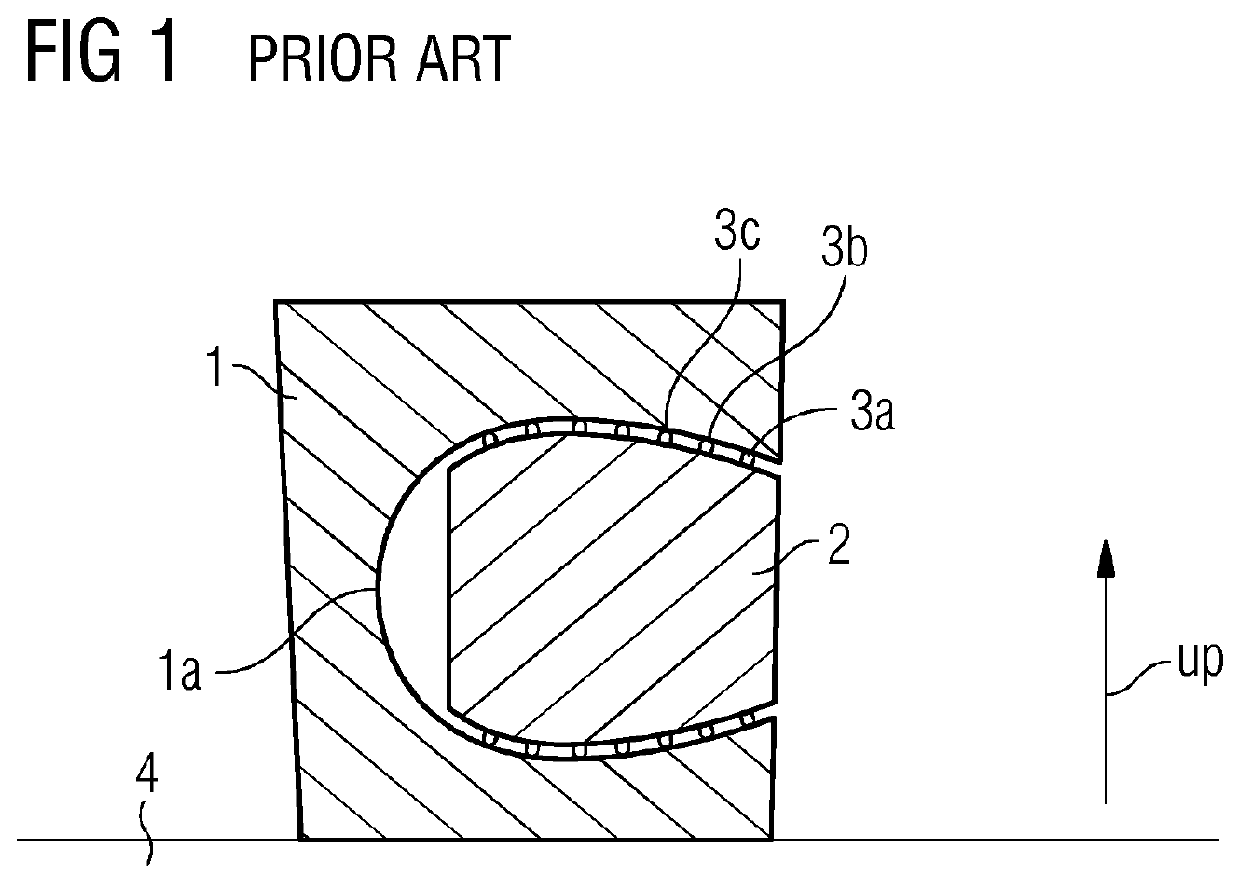
[0051]A schematic representation of a metal part 1 manufactured in an additive manufacturing method is shown in FIG. 1. The metal part is for example a casing and includes a cavity 1a within its body. The part 1 is formed by being built up on a layer-by-layer manner on a baseplate 4 in a manner which will be well known to those skilled in the art.

[0052]A bulk support structure 2 is provided within the cavity 1a of the part 1. The bulk support is arranged to be built relatively quickly during the additive layer manufacture but to have sufficient strength to resist the loads from the part 1 and, for example to resists geometric distortion of the part 1. The skilled person will appreciate that the support 2 may have any convenient (optimised) form and could be a solid or for example a lattice or honeycomb structure.

[0053]To ensure that the support 2 can be removed from the component 1 after manufacture it is provided with an interface 3 which forms a distinct “break line” between the s...


PUM

PropertyMeasurementUnit
distanceaaaaaaaaaa
centre-to-centre distanceaaaaaaaaaa
thicknessaaaaaaaaaa

Abstract

A method of additive manufacturing metallic components, the method includes: forming a component in a layer by layer process, the component being formed integrally with at least one non-perforated support structure to be separated from the component after the layer by layer process, the support structure being formed with at least one wall that is non-perforated; and wherein after completion of the layer by layer process, the method includes exposing the component and support structure to at least one thermal pulse so as to weaken, or break, the interface(s) between the support structure and component prior to removal of the support.

Description

CROSS REFERENCE TO RELATED APPLICATIONS[0001]This application is the US National Stage of International Application No. PCT / EP2018 / 051733 filed Jan. 24, 2018, and claims the benefit thereof. The International Application claims the benefit of GB Application No. 1703238.4 filed Feb. 28, 2017. All of the applications are incorporated by reference herein in their entirety.FIELD OF INVENTION[0002]The present invention relates to additive manufactured metallic components and in particular to methods for additive manufacturing metallic components involving the removal of support structures from such components.BACKGROUND OF INVENTION[0003]Additive Manufacturing is a group of processes characterised by manufacturing three-dimensional components by building up substantially two-dimensional layers (or slices) on a layer by layer basis. Each layer is generally very thin (for example between 20 to 100 microns) and many layers are formed in a sequence with the two dimensional shape varying on e...

Claims


Application Information

Patent Timeline
Patent Type & Authority Patents(United States)
IPC IPC(8): B22F10/20B33Y10/00B33Y30/00
CPCB22F10/20B33Y10/00B33Y30/00C21D1/30C22F1/10C22F1/11B22F2998/10B22F2999/00B29C64/40Y02P10/25B22F10/28B22F10/64B22F10/47B22F10/66B33Y40/20B22F2003/247B22F2201/32B22F2201/50B22F2003/248B21D26/06B22F3/24B23D79/005B22F10/00
Inventor ILLSTON, TREVOR JOHNVORA, PRATIK YATIN
Owner SIEMENS ENERGY GLOBAL GMBH & CO KG
Why Eureka
Try Eureka