
Gas injectors and wafer processing apparatuses having the same

a technology of injectors and wafers, which is applied in the direction of chemical apparatus and processes, coatings, chemical vapor deposition coatings, etc., can solve the problems of deteriorating achieve the effect of improving the performance of semiconductor devices, uniform temperature, and reducing the cleaning performance difference between vertically stacked wafers within the process chamber

Active Publication Date: 2021-06-01
SAMSUNG ELECTRONICS CO LTD
View PDF32 Cites 0 Cited by
  • Summary
  • Abstract
  • Description
  • Claims
  • Application Information

AI Technical Summary

Benefits of technology

This design ensures uniform temperature and flow rates across the wafers, reducing performance differences and enhancing the cleaning process, thereby improving the quality and consistency of semiconductor devices.

Problems solved by technology

However, a temperature difference between process gases sprayed from the spray holes along a vertical direction may generate a cleaning performance difference, thereby deteriorating a performance of a semiconductor device.

Method used


Image

  • Gas injectors and wafer processing apparatuses having the same
  • Gas injectors and wafer processing apparatuses having the same
  • Gas injectors and wafer processing apparatuses having the same

Examples


Embodiment Construction

[0040]Hereinafter, some example embodiments will be explained in detail with reference to the accompanying drawings.

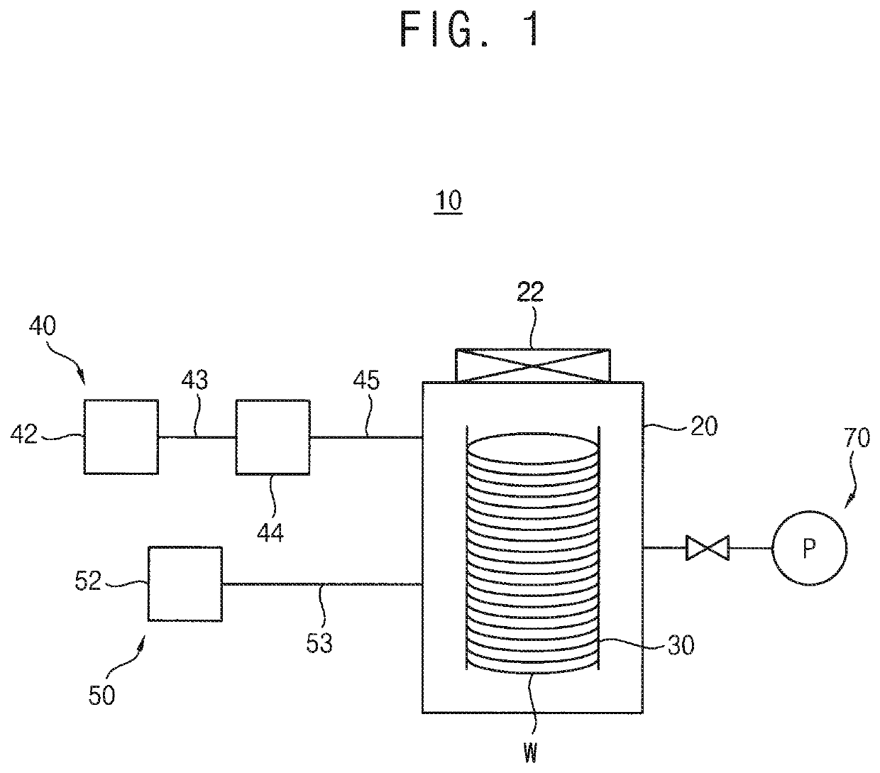
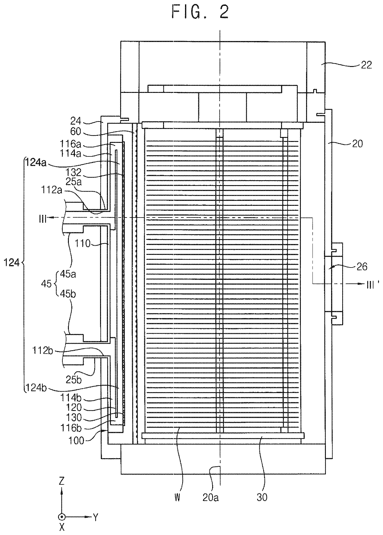
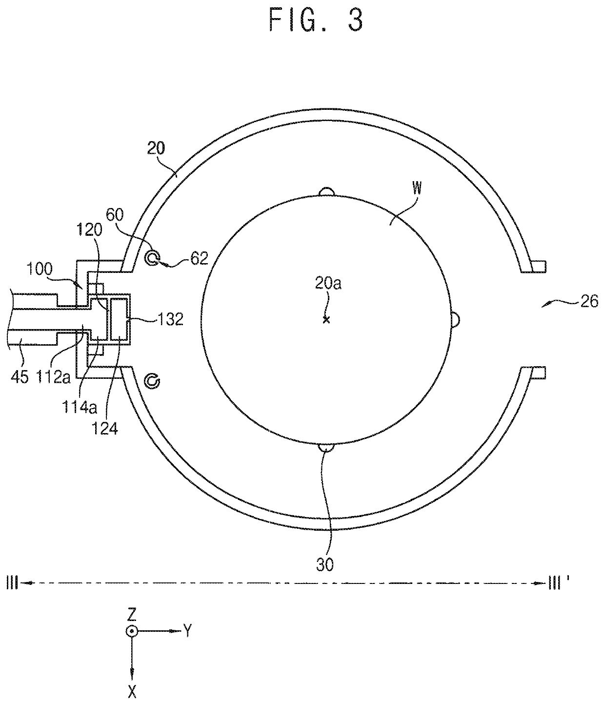
[0041]FIG. 1 is a block diagram illustrating a wafer processing apparatus in accordance with some example embodiments. FIG. 2 is a cross-sectional view illustrating a process chamber in FIG. 1. FIG. 3 is a cross-sectional view taken along the line III-III′ in FIG. 2. FIG. 4 is a cross-sectional view illustrating a flow of a process gas supplied through a gas injector in FIG. 2. FIG. 5 is a perspective view illustrating the gas injector in FIG. 2. FIG. 6 is an exploded perspective view illustrating the gas injector in FIG. 5. FIG. 7 is a perspective view taken along an extending direction of the gas injector in FIG. 5. FIG. 8 is a side view illustrating the gas injector in FIG. 7. FIG. 9 is a cross-sectional view illustrating a first distribution passage of the gas injector in FIG. 5. FIG. 10 is a cross-sectional view illustrating another example of a first distribution...


PUM

PropertyMeasurementUnit
aspect ratioaaaaaaaaaa
lengthaaaaaaaaaa
distanceaaaaaaaaaa

Abstract

A gas injector includes first and second gas introduction passages extending in a first direction toward a central axis of a process chamber respectively, a first bypass passage extending from the first gas introduction passage in a second direction that is substantially perpendicular to the first direction, a second bypass passage extending from the second gas introduction passage in a reverse direction to the second direction, a first distribution passage isolated from the first bypass passage in the first direction and extending from an outlet of the first bypass passage in the reverse direction to the second direction, a second distribution passage isolated from the second bypass passage in the first direction and extending from an outlet of the second bypass passage in the second direction, and a plurality of spray holes in an outer surface of the first and second distribution passages and configured to spray the process gas.

Description

CROSS-REFERENCE TO RELATED APPLICATION[0001]This application claims priority under 35 U.S.C. § 119 to Korean Patent Application No. 10-2018-0047714, filed on Apr. 25, 2018 in the Korean Intellectual Property Office (KIPO), the contents of which are herein incorporated by reference in their entirety.BACKGROUND1. Field[0002]Some example embodiments relate to gas injectors and wafer processing apparatuses. More particularly, some example embodiments relate to gas injectors configured to supply a process gas into a process chamber and wafer processing apparatuses including the same.2. Description of the Related Art[0003]In semiconductor manufacturing processes, a cleaning process may be performed on a plurality of vertically stacked wafers within a batch type chamber to remove a native oxide layer on a wafer surface. A shower head having a plurality of spray holes formed therein may be used as the gas injector for cleaning process. However, a temperature difference between process gases...

Claims


Application Information

Patent Timeline
Patent Type & Authority Patents(United States)
IPC IPC(8): H01L21/67C23C16/52C23C16/455C23C16/02H01L21/673
CPCC23C16/52C23C16/0227C23C16/45565H01L21/67248H01L21/67303H01L21/67028B08B5/02C23C16/45578C23C16/4584H01L21/67017H01L21/67098
Inventor LEE, JONG-HYUNKIMKIM, WOO-JAERYU, SEUNG-MINUH, JI-HO
Owner SAMSUNG ELECTRONICS CO LTD
Learn More