
Feedforward dynamic and distributed energy storage system

a distributed energy storage and dynamic technology, applied in the field of energy storage systems, can solve the problems of reducing the efficiency of the energy storage system, the design of the building has not changed substantially to truly leverage, and the prior art of modular construction is particularly sensitive to the cost of energy interconnection. to achieve the effect of reducing the upfront capital cos

Active Publication Date: 2021-05-18
GURIN MICHAEL
View PDF3 Cites 4 Cited by
  • Summary
  • Abstract
  • Description
  • Claims
  • Application Information

AI Technical Summary

Benefits of technology

The present invention is a distributed and decoupled energy storage system that reduces upfront capital costs and installation costs for modular buildings. It optimizes energy delivery from both local and remote sources and minimizes energy transmission pathway power rating by leverage of strategic and distributed placement of energy storage devices with high peak demand energy consumers. The invention also provides easy access to energy storage devices by integrating them with pocket doors or swinging doors hidden by covers with ion wind generators. The system achieves this by leveraging the high surface area of the energy storage devices to maximize convective heat transfer while remaining virtually silent due to the lack of mechanical air flow methods.

Problems solved by technology

Prior art within modular construction, as well as 3d-printed buildings, are particularly sensitive to the cost of energy interconnects (e.g., electricity, hot-water, cold-water, etc.).
The high-peak demand of energy consumers leads to substantially over-sizing of virtually all energy production and transmission equipment, that leads to a corresponding increase in upfront capital costs having a bigger impact in modular construction though in fact in virtually all types of building construction.
However, the design of buildings has not changed substantially to truly leverage and take advantage of energy distribution advances such as advance energy storage, wireless power, and other advance materials and solid-state electronics capabilities.
Therefore, modular construction has only incrementally reduced the cost of construction and systems leveraging the new technologies actually increase the capital cost of the total system solution rather than reduce capital costs.

Method used


Image

  • Feedforward dynamic and distributed energy storage system
  • Feedforward dynamic and distributed energy storage system
  • Feedforward dynamic and distributed energy storage system

Examples


Embodiment Construction

[0025]Here, as well as elsewhere in the specification and claims, individual numerical values and / or individual range limits can be combined to form non-disclosed ranges.

[0026]Exemplary embodiments of the present invention are provided, which reference the contained figures. Such embodiments are merely exemplary in nature. Regarding the figures, like reference numerals refer to like parts.

[0027]The invention significantly increases the daily cycles of charge / discharge in order to reduce the time duration required to achieve a financial return not only at the component level but most importantly at the system level.

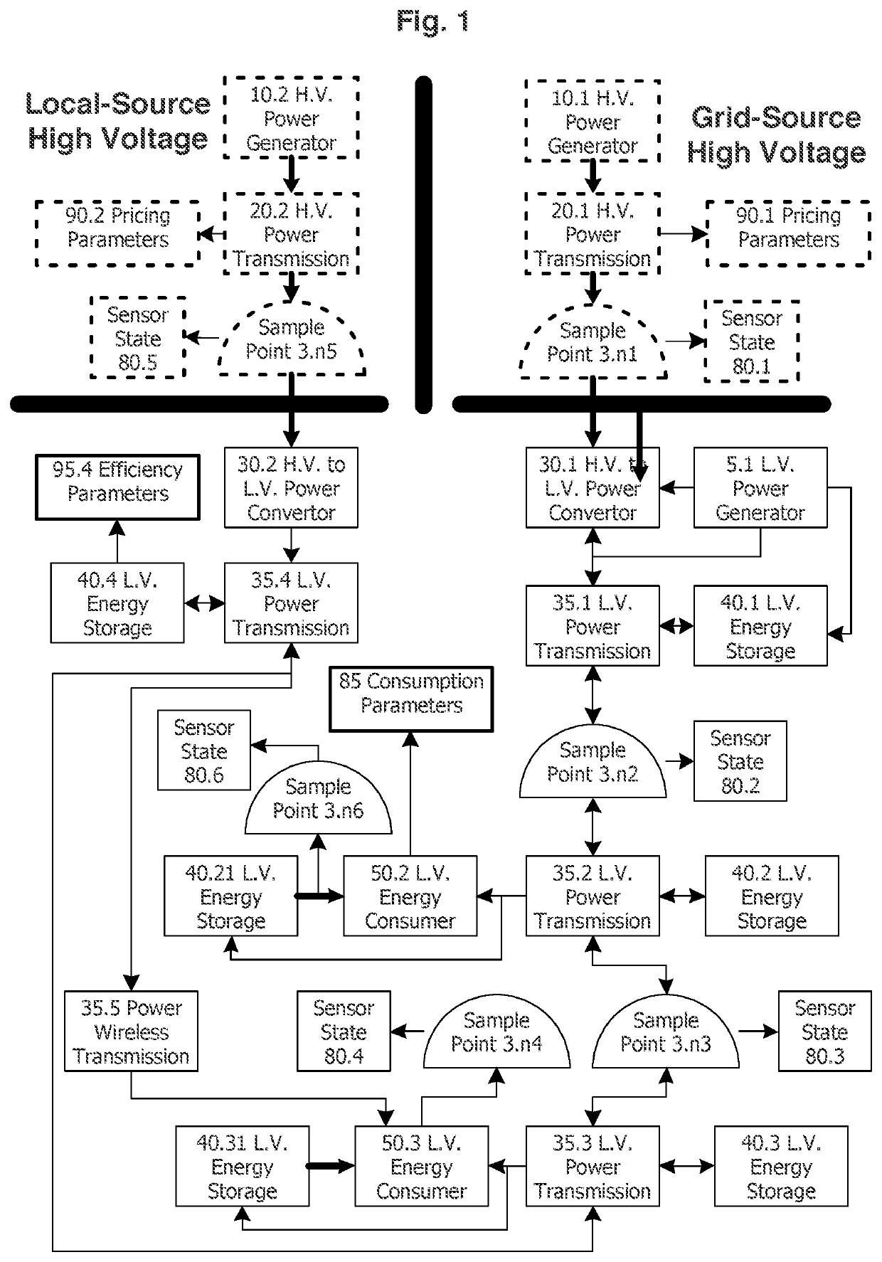
[0028]Turning to FIG. 1, FIG. 1 depicts the interconnection within a modular building as well as the external interconnections from a locally co-located “local-source high-voltage” or “LSHV” energy source and / or a centralized (i.e., not co-located) “grid-source high-voltage” or “GSHV” energy source. It is understood that the LSHV can be in close physical proximity such as ...


PUM


Abstract

A system and method for energy distribution leveraging dynamic feedforward allocation of distributed energy storage using multiple energy distribution pathways to maximize load-balancing to accelerate return on investment, reduce system energy consumption, and maximize utilization of existing energy infrastructure particularly for modular construction.

Description

FIELD OF INVENTION[0001]The present invention relates to an energy storage system, whether the energy is electrical or thermal, with coordinated charging and discharging via a feedforward control system through at least energy flow pathways to minimize system installed cost while maximizing energy efficiency. The implementation of the inventive system is of particular importance in modular construction, 3d-printed buildings, and hyper-energy efficient buildings.BACKGROUND OF INVENTION[0002]Prior art includes the stationary placement of energy storage system(s) within a utility electric grid or within buildings for decoupling power generation from power consumption, such as in particular the creation of intermittent renewable energy (e.g., solar, wind) producers. The integration of particularly solar panels into buildings of all types are done solely in an incremental manner along with the energy storage system. This method has minimal impact in reducing the costs of total building s...

Claims


Application Information

Patent Timeline
IPC IPC(8): H02J3/28H02J3/12H02J3/38
CPCH02J3/28H02J3/12H02J3/386Y02E10/76H02J1/14
Inventor GURIN, MICHAEL
Owner GURIN MICHAEL
Learn More